D
GB
F
E
11
96460-05.2022-DGb
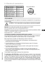
A
B
Fig. 7
Fig. 8
4.6 Flange shut-off valves (HP/LP)
CAUTION
Risk of injury.
The compressor must be depressurized through connections A
and B before commencing any work and prior to connecting to the
refrigerant system.
4
|
Compressor assembly
Tube preparation:
The tube has to be sawn in a right angle. An angular tolerance of ± 1° is permissible.
Slightly trim the pipe ends inside and outside. For thin walled steel pipes or soft pipes made of
nonferrous metal, reinforcing sleeves have to be used.
Pipe assembly:
Push union nut (5) and cutting ring (3) onto pipe (2). Insert pipe into socket (6) as far as it will go and
firmly press against pipe stop, otherwise incorrect assembly. Hand tighten union nut until socket,
cutting ring and union nut are locked. Tighten union nut 1
1
/
2
turns using a spanner wrench. The
cutting ring is noticeably locked to the socket face (for assembly inside pipe connection, hold up
valve with a spanner wrench). This should cause the cutting ring with its cutting edges (1) to cut into
the pipe resulting in a visible collar. In order to stick to the turns we recommend using marking lines
on union nut and pipe. After assembly, it is necessary to check the collar. The gasket must not be
damaged. At least 80 % of the cutting face has to be covered. After check-up, screw on and tighten
again as described above.
4.5 Pipes
Pipes and system components must be clean and dry inside and free of scale, swarf and layers of
rust and phosphate. Only use hermetically sealed parts.
Lay pipes correctly. Suitable vibration compensators must be provided to prevent pipes being
cracked and broken by severe vibrations.
Ensure a proper oil return.
Keep pressure losses to an absolute minimum.


