8
Service Manual for RESmart
®
CPAP and AutoCPAP V1.5
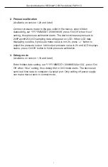
4. Malfunction and Countermeasure
4.1 Malfunction Determination
Страница 1: ...RESmart CPAP and AutoCPAP System Service Manual...
Страница 2: ...ction 3 2 Structure 4 2 1 Outer Illumination 4 2 2 Inner Construction 4 2 2 Spare Part 4 3 Software 5 3 1 Upgrade 5 3 2 Hidden Function 6 4 Malfunction and Countermeasure 8 4 1 Malfunction Determinati...
Страница 3: ...ive airway pressure devices designed for the treatment of adult obstructive sleep apnea OSA only This service manual is intended only for manufacturer authorized service personnel Maintenance actions...
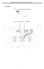
Страница 4: ...ion 2 2 Inner Construction See appendix A 2 3 Spare Part See appendix B Handle DisplayScreen Humidifier Controller User Buttons Air Outlet Humidifier Power Medical Product Note bottom AC Inlet SD Card...
Страница 5: ...tware 1 Request copy of upgrade file prior to starting your upgrade copy on to new SD card 2 Power off RESmart CPAP AutoCPAP device then insert new SD Card 3 Press and hold both Pressure Start Stop Bu...
Страница 6: ...nd restore the unit to initial factory default settings enter the Patient Menu by depressing ramp for 3 seconds or more Advance the menu using the sign until you reach the date option Manually change...
Страница 7: ...a will appear on LCD When LCD data displaying is stable if pressure meter value is not 20 press button to adjust the pressure output Until output pressure value is 20 and LCD displays stable press On...
Страница 8: ...8 Service Manual for RESmart CPAP and AutoCPAP V1 5 4 Malfunction and Countermeasure 4 1 Malfunction Determination...
Страница 9: ...em 14 Blower overheats The temperature of blower is too high or the blower temperature sensor is damaged 15 Possible damage to temperature sensor Restart device if singular occurrence 16 Lack of hardw...
Страница 10: ...device Fig A Main board backside Fig B Fig A Specification of canal 1 Hole 1 on sensor YL 2mm 4mm L12cm 2 Hole 2 on sensor LL 2mm 4mm L12cm 3 Hole 1 on sensor LL 2mm 4mm L8cm Table 1 Fig B Outlet left...
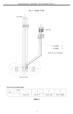
Страница 11: ...mart CPAP and AutoCPAP V1 5 Fig C Power PCBA front side Fig D Wire connecting on power PCBA Sockets figuration Fig E Power supply connecting Blue Brown AC Socket 3 pin plug 6 pin plug 2 pin plug Reed...
Страница 12: ...12 Service Manual for RESmart CPAP and AutoCPAP V1 5 Fig F Power supply to humidifier Connecting relationship Table 2...
Страница 13: ...13 Service Manual for RESmart CPAP and AutoCPAP V1 5 2 Humidifier Fig G Humidifier PCBA back side Fig H Power supply to humidifier...
Страница 14: ...Service Manual for RESmart CPAP and AutoCPAP V1 5 Fig I Heater PCBA Connecting relationship Table 3 3 pin plug Black Black Orange Orange Gray Gray Blue Blue 4 pin plug Power Reed to Humidifer Heater P...
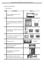
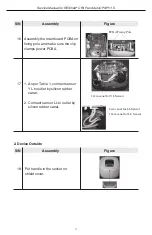
Страница 15: ...shield bottom 2 Insert humidifier power supply reed on the shield bottom as per Fig E and F 3 Assembly the humidifier locker and button spring 4 Put fixing on the spring and fix by screw 2 3mm 8mm 5...
Страница 16: ...ect all plugs Clean up the wire 11 Connect outlet to blower connector fix by clip 12 Connect blower to connector and fix by clip Put the integrated one in the right place 13 Covered by foam cover and...
Страница 17: ...e main board PCBA on fixing pole and make sure the clip clamps power PCBA 17 1 As per Table 1 connect sensor YL to outlet by silicon rubber canal 2 Connect sensor LL to outlet by silicon rubber canal...
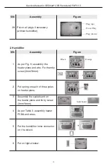
Страница 18: ...4 3mm 8mm 20 Assembly the infrared window 21 Assembly and fix the panel 23 Put on the key button 24 Assembly shield cover on the bottom adjust the position of outlet and make sure it is clamped in th...
Страница 19: ...Fig H assembly the heater plane and wire Fix them by screw 3mm 8mm 2 Put spring on each of three poles on heater plane 3 Assembly the scaleboard on the heater plane and fix by screw 3mm 8mm 4 As per...
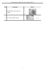
Страница 20: ...20 Service Manual for RESmart CPAP and AutoCPAP V1 5 S N Assembly Figure Screw 7 Assembly the inner and outer shield 8 Fix on screw M3 10mm...
Страница 21: ...and AutoCPAP V1 5 Appendix B Spare Part Configuration S N Name Qty Figure 1 Shield Cover 1 2 Handle 1 3 Handle Fixing 2 4 Shield Bottom 1 5 Humidifier Clip 1 6 Humidifier Locker 1 7 Humidifier Fixing...
Страница 22: ...ame Qty Figure 10 Outlet 1 11 PCBA Fixing 2 12 Infrared Window 2 13 Panel 1 14 Humidifier Outer Shield 1 15 Humidifier Inner Shield 1 16 Light Window 1 17 Pole Platelet 1 18 Humidifier Power Plug 1 19...
Страница 23: ...P V1 5 S N Name Qty Figure 21 Humidifier Plug right up 1 22 Humidifier Plug right down 1 23 Device Pad 6 24 Blower Connector 1 25 Humidifier Inner Connector 1 26 Key Button 1 27 Humidifier Scaleboard...
Страница 24: ...e Filter Cover 4011120801 1 PC Plastic Main Device Shield Back 4011120901 1 PC Plastic Main Device Outlet 4011123001 1 Set Plastic Main Device PCBA Fixing 40111 1301 2 PC Plastic Main Device Infrared...
Страница 25: ...Name S N Qty Unit Classify Use Humidifier Inner Connector 4012110901 1 PC Rubber Humidifier Screw 1 8 PC Screw All Screw 2 9 PC Screw All Sunk Screw 4 PC Screw Main Device Filter 1 PC Accessory All Po...
Страница 26: ...ase visit our Patient Portal at www 3Bproducts com 3B will issue an RMA Return Merchandise Authorization within 24 hours of receipt of written notification of a failed or defective unit Failed defecti...
Страница 27: ......