


24
Service Manual for RESmart
®
CPAP and AutoCPAP V1.5
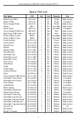
Part Name
S/N
Qty
Unit
Classify
Use
Main Board PCBA
20211261
1
PC
PCBA
Main Device
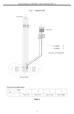
Heater PCBA
20212-41
1
PC
PCBA
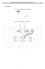
Humidifier
Power Supply PCBA
20311101
1
PC
PCBA
Main Device
Blower
40211
1
PC
Assembly Main Device
Heater Plane
45010101
1
Set
Assembly
Humidifier
Power Supply PCBA Wire
45010201
1
Set
Wire
Main Device
Main Board PCBA Wire
45010301
1
Set
Wire
Main Device
Silicon Rubber Canal
50224
1
PC
Assembly Main Device
Silicon Rubber Canal
50224
1
PC
Assembly Main Device
Foam (bottom)
40191-0101
1
PC
Foam
Main Device
Foam (cover)
40191-0201
1
PC
Foam
Main Device
Shield Cover
4011120101
1
PC
Plastic
Main Device
Handle
4011120201
1
PC
Plastic
Main Device
Handle Fixing
40111-0301
2
PC
Plastic
Main Device
Shield Bottom
4011120401
1
PC
Plastic
Main Device
Humidifier Clip
4011120501
1
PC
Plastic
Main Device
Humidifier Locker
40111-0601
1
PC
Plastic
Main Device
Humidifier Fixing
40111-0701
1
PC
Plastic
Main Device
Filter Cover
4011120801
1
PC
Plastic
Main Device
Shield Back
4011120901
1
PC
Plastic
Main Device
Outlet
4011123001
1
Set
Plastic
Main Device
PCBA Fixing
40111-1301
2
PC
Plastic
Main Device
Infrared Window
4011101401
2
PC
Plastic
Main Device
Panel
4011220101
1
PC
Plastic
Main Device
Power Supply PCBA Fixing
40111-1601
1
PC
Plastic
Main Device
Humidifier Outer Shield
4011122201
1
PC
Plastic
Humidifier
Humidifier Inner Shield
4011122301
1
PC
Plastic
Humidifier
Pole Platelet
40111-2601
1
PC
Plastic
Humidifier
Light Window
4011142401
1
PC
Plastic
Humidifier
Button Spring
4013140101
1
PC
Metal
Main Device
Humidifier Scaleboard
4013130401
1
PC
Metal
Humidifier
Heater Plane Spring
4013140501
3
PC
Metal
Humidifier
Humidifier Power Plug
4012110101
1
PC
Rubber
Main Device
Humidifier Plug (left-up)
4012110201
1
PC
Rubber
Main Device
Humidifier Plug (left-down)
4012110301
1
PC
Rubber
Main Device
Humidifier Plug (right-up)
4012110401
1
PC
Rubber
Main Device
Humidifier Plug (right-down) 4012110501
1
PC
Rubber
Main Device
Device Pad
4012110601
6
PC
Rubber
All
Key Button
4012110701
1
PC
Rubber
Main Device
Blower Connector
4012110801
1
PC
Rubber
Main Device
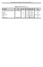
Spare Part List
Содержание RESmart
Страница 1: ...RESmart CPAP and AutoCPAP System Service Manual...
Страница 27: ......