© BlueView Technologies Corp
BlueView BV5000 User Handbook
18
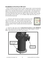
Socket Head
Cap Screw
Connector
Installation of the Pan & Tilt Unit
When mounting the Pan & Tilt Unit to either a tripod, ROV or other structure the
orientation of the base plate must be noted. The base plate contains a 4 bolt hole
pattern of 3.5” diameter which accepts ¼”-20 sized screws. The unit also has an
external mechanical stop which must be installed after the unit is mounted. The
use of this mechanical stop requires two different types of screws when mounting
the base plate to the structure: 3 x ¼”-20 Button Head Cap Screws and 1 x ¼”-
20 Socket Head Cap Screw.
1. Connect to the Pan & Tilt via ProScan and send the unit to
the “Home” Position. The “Home” position is at the center of
rotation of the “Pan” axis. Scans will be centered about this
position. If mounting onto an ROV, the Pan and Tilt should be
mounted with the “Home” position pointed directly away from
the ROV.
2. Mount the base plate with the Socket Head Cap Screw on the OPPOSITE
side of the connector when the Pan and Tilt is in the “Home” position. Use the
Button Head Cap Screws at the other three locations.
Содержание BV5000
Страница 50: ... BlueView Technologies Corp BlueView BV5000 User Handbook 50 Pan and Tilt Outline Drawing Units Inches ...
Страница 51: ... BlueView Technologies Corp BlueView BV5000 User Handbook 51 MB2250 45 Outline Drawing Units Inches ...
Страница 52: ... BlueView Technologies Corp BlueView BV5000 User Handbook 52 MB1350 45 Outline Drawing Units Inches ...


