4000/5000 Modems’ User Guide
Note: Combined GPS and Cellular antennas are available. Contact your local
representative for more details.
To install, make sure you position the antenna so it has line-of-sight with the sky.
Thread the antenna cable so it can reach the front plate of the modem. Then connect
the cable’s connector into the modem’s by screwing it in finger tight. Do not use tools.
Test
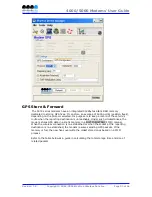
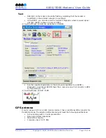
To test your installation, open BVDM and go to File > GPS Settings, then select NMEA
protocol. BVDM will display the GPS information and whether a fix is available or not.
Serial cable
If you are connecting to the modem via serial port, you will need a standard straight
through RS-232 cable with DB9 male to DB9 female connectors.
Ethernet cable
If you are connecting to the modem via the Ethernet port, you will need a crossover
category 5 cable with two 8-pin RJ45 connectors on each end.
Test
In order to visually confirm appropriate usage of cable, check the LED indication on
the Ethernet port located at the rear panel of the modem. The Link LED should be on
when the right cable is used.
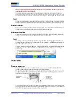
If you’re plugging into a standard PC running Windows XP, Windows will automatically
detect the presence of the modem on its Ethernet port and will popup a message
accordingly:
USB cable
Power source
You will need to provide a 12 VDC nominal power source to the modem (8Vdc to
30Vdc). Please see electrical specifications for more details.
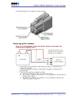
The modem includes a 15-foot power cable with 2A in-line fuse with, on one end, a 4-
pin Molex MiniFit connector that connects to the modem, and stripped wires on the
other end to connect to your power source.
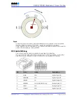
The ignition sense line (white wire) acts as an ON/OFF power switch. The modem will
turn on when the ignition sense line is set between 8 and 30 volts DC. The modem will
turn off if the ignition sense line is less than 5 volts DC.
Revision 1.0
Copyright © 2004-2006 BlueTree Wireless Data Inc.
Page 40 of 44

