DA11ABL-WP-US
QUICK REFERENCE GUIDE
02
www.blustream.com.au
|
www.blustream-us.com
|
www.blustream.co.uk
Dante Controller
Dante Controller software is required in order to setup and configure the DA11ABL-WP-US as well as control your Dante
network. Audinate provide extensive training videos and documentation on their website. This can be found here:
http://www.audinate.com/products/software/dante-controller
Upon connecting your DA11ABL-WP-US to a compatible network, the Dante Controller software should automatically
discover the device. The DA11ABL-WP-US will appear in the Dante Controller with a name denoted with “DA11ABL-WP”.
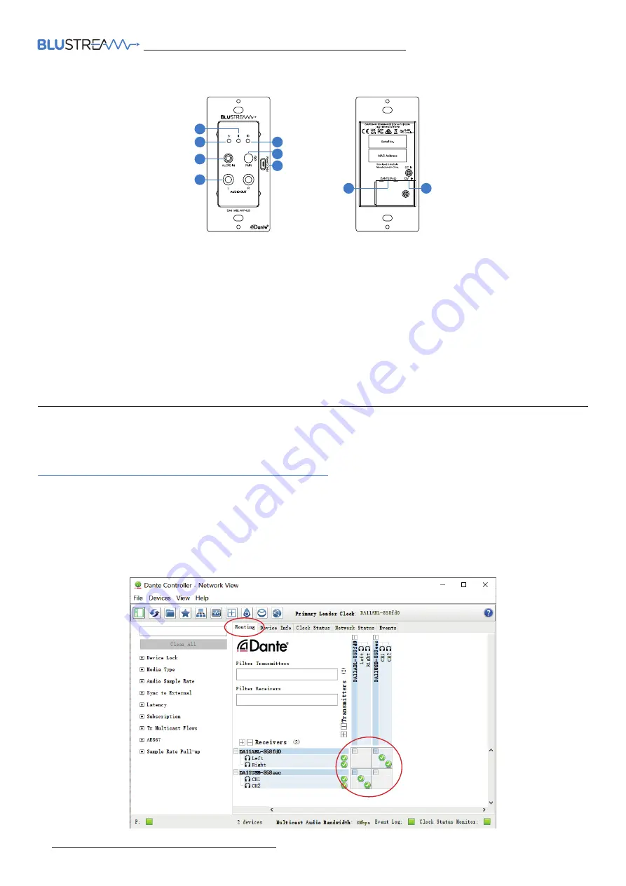
On the “Routing” screen you can create audio routing between Dante transmitters and receivers in your system.
Please ensure your PC is on the same network as your Dante devices. Dante is not able to transmit over WiFi and it is
recommended to hardwire into the Dante network. Having multiple network devices enabled can also confuse the
Dante Controller software so it is recommended to disable WiFi during configuration.
Connections:
1
Bluetooth LED - Illuminates when a Bluetooth connection is active
2
Power LED - Illuminates when the DA11ABL-WP-US is powered on
3
Audio In - Analog audio 3.5mm L/R stereo input jack. Connect to analog audio souce device for audio input
4
Audio Out - Analog audio RCA L/R output. Connect to analog audio amplifier for audio output
5
ID LED - Flashes to assist in identification of the device, controlled via control software or Dante Controller
6
Bluetooth Pair Button - Press to activate Bluetooth Pairing mode. Press and hold for 3 seconds to disconnect Bluetooth
devices. Press 2 times in quick succession to select audio input. Note settings can be adjusted via control software
7
Program Port - Micro USB port to allow PC connectivity for configuration via control software and firmware updates
8
Dante® (PoE) Port - RJ45 connector supporting PoE, connects to Dante® audio network
9
DC Input - Connect to +12VDC power supply (not supplied) if device is not powered via a PoE switch
Front Panel
2
3
4
5
6
7
1
Rear Panel
8
9


