22
o
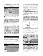
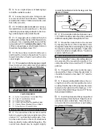
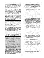
22) Using a modeling knife, remove the cov-
ering from just inside the lines. Using 220 grit
sandpaper, roughen the bottom sides of the can-
non mount. Glue the cannon mount in place using
Kwik Bond 5 Minute Epoxy.
FINAL ASSEMBLY
INSTALLING THE RECEIVER AND BATTERY
o
1) Plug the servo leads into the receiver. Plug
the aileron extension and switch that came with
your radio system into the receiver as well.
o
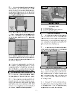
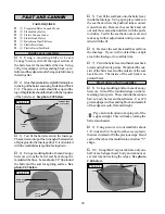
2) Wrap the receiver and battery pack in
foam rubber to protect them from vibration. Po-
sition them just in front of the wing's trailing edge,
on the fuselage floor. Use extra foam pieces to
hold them in position.
When balancing the airplane you may need
to move the battery or receiver forward to
achieve proper balance. In our test airplane, using
a Magnum XL .52 four stroke engine, the battery
and receiver were mounted as per step # 2.
o
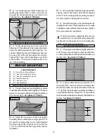
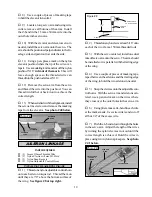
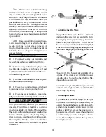
3) Using a 1/16” drill bit, drill a hole through
the side of the fuselage, opposite the muffler, for
the antenna to exit. Route the antenna out of the
fuselage and secure it to the vertical stabilizer us-
ing a rubber band. See figure # 9 below.
INSTALLING THE SWITCH
o
4) Mount the switch to the fuselage side,
opposite the muffler, at the rear of the servo com-
partment. Use the faceplate of the switch itself to
locate at make the necessary cutouts and holes.
Figure # 9
CUT
RUBBER
BAND
MODIFIED SERVO
ARM
ANTENNA
INSTALLING THE FUEL LINES
o
5) Cut to length two pieces of silicon fuel
line. One piece should be connected between
the fuel pickup tube at the tank and to the fuel
nipple on the carburetor. The second piece should
be connected between the pressure/vent tube at
the tank and to the pressure nipple on the muffler.
INSTALLING THE PROPELLER
o
6) Install the propeller recommended for
your engine and secure it in place using the after-
market spinner nut that you purchased separately.
o
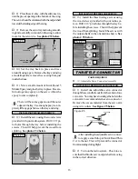
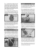
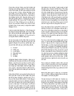
1) It is critical that your airplane be bal-
anced correctly. Improper balance will cause
your plane to lose control and crash. The cen-
ter of gravity is located 3-1/2” back from
the leading edge of the wing, at the fuse-
lage sides. This location is recommended for
initial test flying and trimming. There is a 1/2”
margin forward and aft, but it is not recom-
mended that the center of gravity be located
any further back than 4”. Balance the Blue
Max right side up with the fuel tank empty.
o
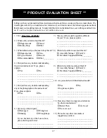
2) Mount the wing to the fuselage. Using
a couple of pieces of masking tape, place them
on the bottom side of the wing 3-1/2” back
from the leading edge, at the fuselage sides.
o
3) Place your fingers on the masking tape
and carefully lift the plane.
o
4) If the nose of the plane falls, the plane is
nose heavy. To correct this first move the bat-
tery pack further back in the fuselage. If this is
not possible or does not correct it, stick small
amounts of weight on the fuselage under the hori-
zontal stabilizer. If the tail of the plane falls, the
plane is tail heavy. To correct this, move the bat-
tery and receiver forward or if this is not pos-
sible, stick weight onto the firewall. When bal-
anced correctly, the airplane should sit level or
slightly nose down when you lift it up with your
fingers.
Once you have flown and trimmed the Blue
Max, the balance point can be moved for-
ward or aft 1/2” to change the flight performance.
Moving the balance point back will cause the Blue
Max to be more responsive, but less stable. Mov-
ing the balance point forward will cause the Blue
Max to be more stable, but less responsive. Do
not fly the Blue Max beyond the recom-
mended balance range or an uncontrollable
crash could result!
BALANCE
TO VERTICAL
STABILIZER


