11
BT-HE-DASHBOARD
User Manual
Unit Section
Unit Name:
Clicking on the Unit name link (ex. Unit1) will take the browser to the Log-in page of the particular encoder.
Placing the cursor over the Unit’s name will display a pop up with key encoder information as shown in Figure 4.1b.
Identify Unit:
When button is selected, it will provide a temporary LED indication on the encoder lasting about 1 minute.
HDE-8C-QAM/IP Series encoders are identified by the Audio LEDs changing one at a time to red starting from
Input # 1 and moving right towards Input #8. The sequence continues on the Video LED row, again starting at
input #1 and moving right. After all LEDs are have turned red they all simultaneously switch back to green and
the cycle begins again.
HDE-8C-DIN Series and AQT8-QAM/IP are identified by the Status LED flashing between red and green.
Name:
This field allows a user-defined encoder name for easier identification.
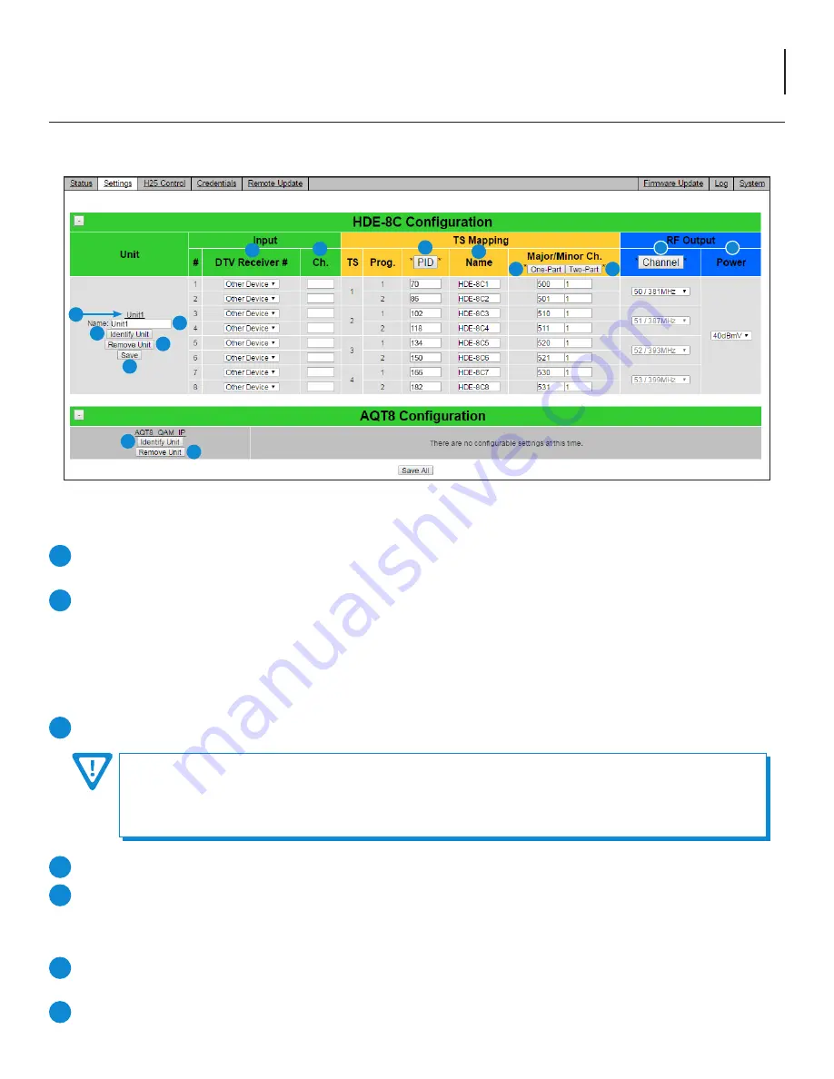
4.2 “Settings” Screen
The “Settings” screen (Figure 4.2) is a “user-configurable” screen where the following input source parameters can be configured:
1
2
3
4
5
To properly name the unit as to avoid issues, the following rules MUST be observed:
1. NO spaces can be used within the name. If a separation is needed, use underscores (ex. 8C_Unit1 )
2. Naming from Unit1 to Unit9 does not require any need for separating/spacing. If the user needs to go beyond this
number, there should be an underscore between the word “Unit” and the number. (ex. Unit_10 )
Remove Unit:
This button deletes the unit from the DASHBOARD’s database. User must select “Save”.
Save:
This button saves any changes made to the Encoder. The “Save All” button at the bottom of the page will save
any changes made to any of the Encoders.
Input Section
DTV Receiver #:
Shows the serial number for each H25 Receiver. The default is "Other Device" until user assigns receiver.
Clicking on the box will display a pop-up menu with serial numbers of available receivers.
Channel (Ch.):
This can be set as channel number for each H25 receiver for valid authorized channels.
6
7
Figure 4.2 - “Settings” Screen
2
2
3
6
7
8
10
11
12
13
9
4
4
5
1


