


Fig. 4
Leitung 1 + 2 = Leitungslänge
Conducter 1 + 2 = Cable length
D
C
O
U
T
LOA
D
1
2
–
+
I
out
/%
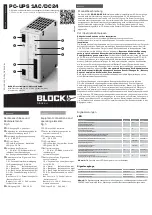
0 20 40 60 80 100 120
0
20
40
60
80
100
U
out
/%
Temp. (°C)
I
N
/%
-25 0 25 50 70
0,0
0,2
0,4
0,6
0,8
1,0
1,2
Auslösen von Standard- Leitungsschutzschaltern
Fig. 4
Kabelquerschnitt (mm²)
0,75
1,5
2,5
Art.-Nr. PC-1024-050-0
Leitungslänge mit LS B2
20 m
40 m
40 m
Leitungslänge mit LS B3
20 m
40 m
40 m
Leitungslänge mit LS B4
20 m
40 m
Die aufgeführten Leitungslängen sind experimentell bei ca. 25° C ermittelt worden. Sie
dienen als Richtwert für die Auslegung der DC-seitigen Absicherung durch Leitungs-
schutzschalter und sollten in der jeweiligen Applikation kundenseitig überprüft werden.
Fast tripping of standard bi-metal circuit breakers
Fig. 4
Cable cross-section (mm²)
0,75
1,5
2,5
Art.-Nr. PC-1024-050-0
Cable length with CB B2
20 m
40 m
40 m
Cable length with CB B3
20 m
40 m
40 m
Cable length with CB B4
20 m
40 m
The specified cable lengths are theoretical values only and were determined in
respect to approx. 25° C. They serve only as a guide for determining the protection
through a standard circuit breaker and must be verified in the respective application.
Ausgangskennlinie
Output characteristic
Verdrahtung
Wiring
Buffered
load
+ -
BUFFERING
ON /OFF
Inpu
t
B
at
. A
lar
m
B
at
. M
ode
B
at
. C
har
ge
Re
mo
te
Re
mo
te
B
at
. C
on
tr
ol
Interface
B
at
. C
on
tr
ol
B
at
ter
y
B
at
ter
y
+ +
-
-
OUT
IN
L N
BAT
BAT
+
+
-
-
+
+
-
-
13 14 24 34 R1 R2
PC-1024-050-0
CTRL
CTRL
+
+ -
-
T
Hinweis:
Eine detaillierte Beschreibung finden Sie
im Handbuch des Gerätes, das auf der
Produktseite unter www.block-trafo.de
kostenlos zum Download bereitsteht.
Notice:
You can download the complete manual with
detailed description from our product site
under www.block-trafo.de
Mounting
Fig. 2
AUF TRAGSCHIENE AUFRASTEN
I) Gerätevorderseite leicht nach oben
drehen
II) Auf Hutschiene aufsetzen
III) Bis zum Anschlag nach unten schieben
IV) Unten gegen die Befestigungsebene
drücken (klick)
V) Leicht am Gerät rütteln, um Verrie-
gelung zu prüfen
Montage
Fig. 2
SNAP ON SUPPORT RAIL
I) Tilt the unit slightly rearwards
II) Fit the unit over top hat rail
III) Slide it downward until it hits the stop
IV) Press against the bottom front side
for locking (click)
V) Shake the unit slightly to check the
locking action
Fig. 2
I
II
III
IV
V
deutsch
english
Battery
modul
Battery
modul
Pin 2 = RxPC
Pin 3 = TxPC
Pin 5 = GND
T
TxPC RxPC
Interface
1
Tx
2
Rx
3
GND
4
+24V
1
Tx
2
Rx
3
GND
4
+24V
Содержание PC-1024-050-0
Страница 5: ......


