Lit. No. B64092, Rev. 09
16
April 15, 2021
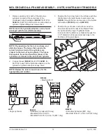
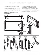
1. Position the front (top) hole in the A-frame with
the middle hole in the pivot beam. Insert cap
screw (
B61331
for 760TR;
50605
for 860TR
and 8600TR) through the top, and secure on the
bottom with washer (
B61203
) and nut (
B61008
).
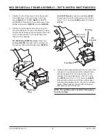
2. Position the pivot beam and A-frame near the
mount locations at the rear of the blade. Position
the pivot beam between the two support ribs until
the connecting points on the beam align with
those on the snowplow.
For 6760TR and 860TR models:
Insert one
bushing (
B16536
) through each mounting hole
and secure them with retaining rings (
B61616
).
Bushing
Retaining
Ring
Retaining
Ring
MOLDBOARD & A-FRAME ASSEMBLY – 760TR, 860TR & 8600TR MODELS
For 8600TR model:
Insert one bushing (
42410
)
through each mounting hole and secure it with a
3/8' x 1-1/2" cap screw (
66439
) and 3/8" locknut
(
91333
).
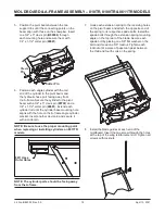
3. Position each angle cylinder with the rod end of the
cylinder in the pivot beam and the hydraulic hose
port facing away from the A-frame. Secure the
cylinder to the pivot beam with a 3/4" x 5" clevis
pin (
95739
) and a 1/4" x 1-1/2" cotter pin (
90601
).
Extend each cylinder rod until the cylinder base
mounting hole aligns with the hole on the A-frame
angle cylinder bracket. Insert another clevis pin
and secure it with a cotter pin.
NOTE: The cylinder ports should be facing away
from the A-frame.
Bushing
Pivot Beam
3/8" x 1-1/2"
Cap Screw
3/8"
Locknut
Содержание 760TR
Страница 2: ......


