501-K00 Page 8/12
MAINTENANCE
VANE REPLACEMENT
NOTICE:
Maintenance shall be performed by qualified technicians
only, following the appropriate procedures and warnings
as presented in this manual.
1. Drain and relieve pressure from the pump and system as
required.
2. Remove the head assembly from the outboard (non-
driven) side of the pump according to steps 1 through 6
in the "Pump Disassembly" section of this manual.
3. Turn the shaft by hand until a vane (14) comes to the
bottom (6 o'clock) position of the rotor. Remove the
vane.
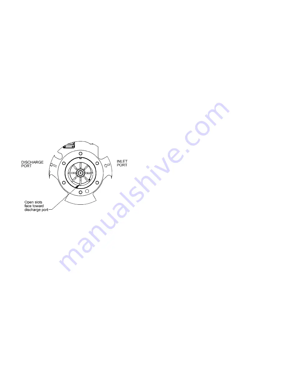
4. Install a new vane (14), ensuring that the rounded edge
is DOWN, and the relief grooves are facing towards the
discharge port. See Figure 7.
5. Repeat steps 3 and 4 until all vanes have been replaced.
6. Reassemble the pump according to the "Pump
Assembly." section of this manual.
Figure 7. Vane Installation
PUMP DISASSEMBLY
NOTICE:
Follow all hazard warnings and instructions provided in
the “Pump Maintenance” section of this manual.
1. Drain and relieve pressure from the pump and system as
required.
2. Remove the outboard head capscrews (21) and slide the
outboard head (23) off the shaft. The bearing (24),
grease seal (104A), mechanical seal stationary seat and
stationary O-ring (153A & 153D) will come off with the
head assembly.
3. To disassemble the outboard head:
a. Remove the bearing cover capscrews (28), bearing
cover (27A) and shims (26) from the outboard head.
b. Evenly tap bearing outer race with a soft-faced drift
punch to remove the mechanical seal stationary seat
(153A), grease seal (104A), and bearing outer race.
4. Carefully pull the rotating seal assembly, consisting of
seal jacket (153C), rotating seal face and rotating O-ring
(153B & 153E) from the shaft. Remove and discard the
rotating O-ring (153E).
5. Carefully remove the disc (71).
6. Clean inboard end of pump shaft thoroughly, making
sure the shaft is free of nicks and burrs. This will prevent
damage to the mechanical seal and grease seals when
the rotor and shaft assembly is removed.
7. Pull the rotor and shaft assembly (13) from the casing
(12). While one hand is pulling the shaft, the other hand
should be cupped underneath the rotor to prevent the
vanes (14) from falling out.
8. Remove vanes (14) and inboard rotating mechanical seal
parts from rotor and shaft assembly.
9. Remove the head capscrews (21) and inboard head (20)
from casing (12). The bearing (24), grease seal (104A),
mechanical seal stationary seat and stationary O-ring
(153A & 153D) will come off with the head assembly.
10. To remove the mechanical seal stationary seat (153A),
grease seal (104A), bearing outer race, and bearing
spring, evenly tap bearing outer race with a soft-faced
drift punch.
11. Carefully remove the disc (71).
12. If necessary, remove the liner (41) by tapping around the
outside diameter of the liner with a hard wood block and
a hammer until it is driven from the casing (12).
13. Remove liner key (74).
PARTS REPLACEMENT
1. Any O-rings removed or disturbed during disassembly
must be replaced with new O-rings.
2. Excessive or continuous leakage from the tell-tale hole in
the bearing cover may be an indication of a damaged
mechanical seal. If a mechanical seal has been leaking, it
is recommended the entire seal be replaced. Refer to
"Troubleshooting" for possible causes of seal leakage.


