Blackmer Page 109-A00 Page 3 of 4
INSTALLATION
NOTICE
This product must only be installed in systems which
have been designed by those qualified to engineer such
systems. The system must be in accordance with all
applicable regulations and safety codes and warn of any
hazards unique to the particular system.
ALIGNMENT ADJUSTMENT
To adjust the alignment of the gear reducer to the pump or
motor, use shims as needed.
COUPLING ALIGNMENT
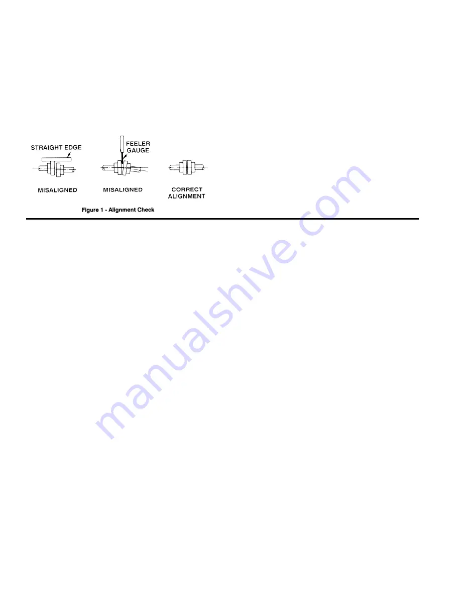
Both angular and parallel coupling alignment MUST be
maintained between the pump, gear, motor, etc. in
accordance with manufacturer’s instructions. Verify coupling
alignment after installation of new or rebuilt pumps. See fig. 1.
1. Parallel alignment: The use of a laser alignment tool or dial
indicator is preferred. If a laser alignment tool or dial indicator
is not available, use a straightedge. Turn both shafts by hand,
checking the reading through one complete revolution.
Maximum offset must be less than .005” (125 microns).
2. Angular alignment: Insert a feeler gauge between the
coupling halves. Check the spacing at 90º increments around
the coupling (four check points). Maximum variation must not
exceed .005” (125 microns). Some laser alignment tools will
check angular alignment as well.
3. Replace the coupling guards after setting alignment.
MAINTENANCE
NOTICE:
Maintenance and troubleshooting must be done by an
individual experienced with pump and reducer
maintenance and the type of system involved.
NOTICE:
To avoid possible entanglement in moving parts do not
lubricate pump bearings, gear reducer or any other parts
while the pump is running
.
CAUTION
: The normal full load operating temperature of the
gearcase is 180ºF (82ºC) – too hot to touch with the bare hand.
LUBRICATION
Gear reducers are not lubricated at the factory. Oil MUST
be added before starting the pump.
Horsepower calculations for Blackmer reducers are based on
75°F (24°C) ambient air temperature; 200°F (93°C) maximum
oil temperature using synthetic oil.
Blackmer recommends using synthetic oil with oxidation
inhibitors and is compatible with Buna elastomers. Use
synthetic oil AGMA Viscosity Grade 4 or ISO Viscosity Grade
150 such as Mobil SHC 629
, Mobil SHC 630
, Shell Omala S4
GX 150, Castrol Isolube EP 150 or equivalent.
To add oil to the gear reducer:
1. Remove the oil level plug (29D) and the fill and vent plug
(76C).
NOTE
: The vent fitting in the fill plug (76C) should
be kept clean to prevent expansion from forcing oil leaks at
the shaft.
2. Add oil through the filler hole until oil runs out of the oil level
hole – approximately 0.5 qt. (0.47 l) depending on the
orientation of the reducer mounting.
3. Replace the oil level plug and the fill and vent plug.
4. After the first two weeks of operation, the oil should be
drained, the gearcase flushed, and new oil added.
For normal operation, the oil should be changed every six
months or 1000 hours, whichever is shorter. If operation is
accompanied by frequent and wide changes in temperature,
or if the unit operates in an unusually moist or dusty
atmosphere, the oil should be changed every 500 hours or
every three months.
REDUCER DISASSEMBLY
The foot mounted gear reducer can usually be removed from
its unit assembly without disturbing the motor or pump
mounting.
1. Take apart the couplings and remove the capscrews in the
foot mount.
2. Once the couplings are apart and the capscrews are
removed, the reducer can be lifted away from the pump
and motor.
3. Remove the cover capscrews (112 & 112A). NOTE: The
gearcase cover is located on the gearcase with two (2)
dowel pins (38). These pins remain in the gearcase.
4. After the capscrews have been removed, insert a wedge
between the projecting lugs on the gearcase cover and tap
lightly until the cover loosens and can be removed from the
casing.
5. Remove the cover gasket (111).
6. The pinion & shaft (input shaft) (102) is a one-piece
assembly and does not come apart. If necessary, the
bearings (24 & 24A) can be removed from the shaft with
the use of a bearing puller or arbor press.
7. To remove the gear (101) and bearings (24B & 24C) from
the output shaft (125), use a gear puller or arbor press.
Support the assembly on the gear and press the shaft out
of the gear and bearings.


