102-A00 page 9/16
MAINTENANCE
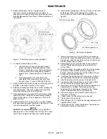
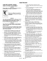
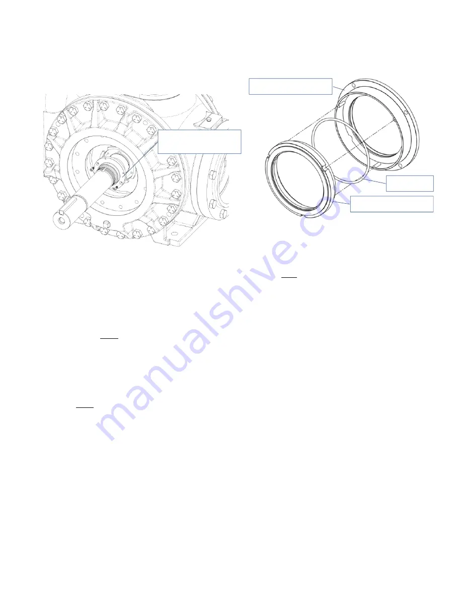
10. Inspect shaft sleeve (154A). If replacement is
necessary, remove capscrews (155), set aside. If
necessary, use seal mounting holes as jackscrew holes
to assist disassembly. See Figure 7 Discard stationary O-
ring (154B).
Figure 7 – Shaft sleeve removal and installation
11. To install new shaft sleeve (154A):
a. Lubricate inner O-ring (154B) using bearing
grease identified in lubrication section of this
manual. Install sleeve over shaft while aligning
mounting holes with corresponding threaded
holes in rotor. Sleeve should mount flush with
rotor
b. Place small amount of Loctite # 220 onto
capscrews (155), thread fully into rotor holes
through sleeve. Torque to 200 inlbf (22.6 Nm).
12. Lightly lubricate shaft sleeve surface with bearing grease
identified in lubrication section of this manual.
13. Install seal rotating assembly minus carbon rotating face
onto shaft sleeve. Take care to align mounting holes
with corresponding holes on shaft sleeve.
14. Place small amount of Loctite # 220 onto seal mounting
capscrews (153J). Install into corresponding threaded
holes on seal sleeve. Torque capscrews (153J) to 20
inlbf (2.25 Nm).
15. Lightly lubricate inner O-ring (153L) on carbon rotating
face using bearing grease identified in this manual. Take
care to keep seal face free from grease.
NOTICE
:
Use ONLY recommended grease.
Using petroleum
based grease or oil to lubricate seal O-rings WILL cause
seal O-ring damage and subsequent product leakage.
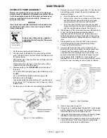
16. Install carbon rotating face (153F) and O-ring (153L) over
shaft sleeve (154A) while aligning drive notches in
carbon with drive pins in seal rotating assembly. (see
figure 8)
Figure 8 – Seal carbon alignment
17. Install a new stationary O-ring (153D) in the stationary
seat (153B). Clean the polished face with a clean tissue
and alcohol. Push the seat fully into the hub seal recess
with the polished face outward.
18. Apply small amount of Loctite # 220 to seal retaining
screws. Install seal retaining screws and washers
(153Q, 153R).
19. If removed, press the grease seal(104A) into the grease
seal carrier (104b) with the lips facing toward the
bearing. Place the grease seal carrier (104B) with new
O-ring (104C) into the hub (20C).
20. Hand pack the ball bearing (24) with grease. Refer to
the "Lubrication" section for the recommended grease.
21. Install the bearing into the recess of the hub (20C).
22. Temporarily attach the bearing cover (27) and gasket
(26) to hub and hand tighten capscrews (28).
23. Install new hub O-ring (72B) and carefully install the hub
assembly (20C) on head. Install and tighten hub
capscrews (21A) torquing as indicated in the “Torque
Table” in maintenance section of this manual
24. Remove bearing cover and install locknut and new
lockwasher until snug.
25. Loosen locknut on the outboard end of pump
26. Tighten locknut on near side
27. Repeat steps 7-24 for seal and/or bearing replacement of
opposite side of pump
28. Adjust locknuts per “Locknut Adjustment” instructions in
maintenance section of this manual
154A
Shaft
Sleeve,
155
Retaining
Screws
(2)
153F
Rotating
Seal
Face
153G
Seal
Spring
Holder
153L
O
‐
ring


