
5
The bypass valve and piping must be of adequate size to
accommodate the full flow from the pump when the discharge
line is closed. Shut off valves and couplings must be provided
on both sides of the pump and bypass valve for removal and
servicing. The pump internal relief valve is factory set at
approximately 125 psi (8.6 bar).
Refer to Blackmer Bypass Valve Installation and Maintenance
Instructions for bypass valve installation, setting and
adjustment procedures.
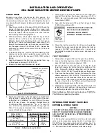
PUMP ROTATION
NOTICE:
CONFIRM CORRECT PUMP ROTATION BY CHECKING
THE PUMP ROTATION ARROWS RESPECTIVE TO PUMP
DRIVER ROTATION.
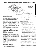
TO CHANGE PUMP ROTATION
Blackmer
CRL4A
motor driven pump models are equipped
with a double ended rotor and shaft, enabling them to be
driven from either shaft end. To change rotation, rotate the
pump 180 degrees so the opposite shaft becomes the driven
shaft. The shaft protector (186) MUST be mounted over the
non-driven shaft end.
START UP PROCEDURES
NOTICE:
CONSULT THE "GENERAL PUMP TROUBLESHOOTING"
SECTION OF THIS MANUAL IF DIFFICULTIES DURING START
UP ARE EXPERIENCED.
1. Start the motor.
2. If priming does not occur, shut off the pump and close the
pump discharge. Open the bleed valve on the pump
discharge gauge hole until “snow” appears at the exhaust.
Close the bleed valve, open the discharge line and start
the pump. Repeat if necessary.
3. Check the pressure gauges to ensure the system is
operating within expected parameters. Record the gauge
readings in the "Initial Start Up Information" section of this
manual for future reference.
4. Inspect piping, fittings, and associated system equipment
for leaks, noise, vibration and overheating.
5. Check the flow rate to ensure the pump is operating within
the expected parameters. Record flow rate in the “Initial
Start Up” section of this manual for future reference.
6. Close the discharge valve and check the differential
pressure across the pump. It must not exceed the
pressure setting of the external bypass valve.
7. With the discharge valve still closed, momentarily close the
manual shut-off valve in the bypass return line to check the
pump relief valve. The pressure must be at least 25 psi
(0.7 - 1.4 bar) higher than the operating pressure or the
system pressure control valve setting. Refer to “Relief
Valve Setting and Adjustment” section of this manual.
8. The external bypass valve must always be set at least 25
psi (1.7 bar) lower than the pump internal relief valve.
NOTE: The normal operating pressure must be at least 5 -
15 psi (0.3 -1.0 bar) less than the external bypass setting.
Pump speeds which result in higher pressures (nearing the
valve setting) forces the liquid to be recirculated, creating
excessive wear on the pump and equipment.
PRE-START UP CHECK LIST
1. Inspect complete piping system and supports to ensure
that no piping loads are being placed on the pump.
2. Install pressure gauges in the
1
/
4
" NPT intake and
discharge ports located on the pump casing to check pump
performance after start-up.
3. Build pressure in the pump by SLOWLY cracking the valve
in the discharge line. When the internal pump pressure
equals tank pressure, check for system leaks.
4. Ensure all valves and fittings in piping system are in the
start-up or operating positions.
5. Jog the pump motor to verify proper pump rotation.
INSTALLATION AND OPERATION
CRL BASE MOUNTED MOTOR DRIVEN PUMPS
RELIEF VALVE SETTING AND ADJUSTMENT
The factory relief valve pressure setting is marked on a metal
tag attached to the valve cover. It is recommended the relief
valve be set at least 10 - 20 psi (0.7 - 1.4 bar) higher than the
operating pressure or the system pressure control valve
setting.
Hazardous pressure
can cause personal
injury or property
damage.
I
NCORRECT SETTINGS OF THE PRESSURE
RELIEF VALVE CAN CAUSE SYSTEM
COMPONENT FAILURE, PERSONAL INJURY
AND PROPERTY DAMAGE.
OPERATING PUMP AGAINST A
CLOSED VALVE CAN CAUSE
SYSTEM COMPONENT FAILURE,
PERSONAL INJURY AND PROPERTY
DAMAGE.
Hazardous pressure
can cause personal
injury or property
damage.
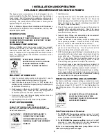
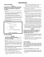
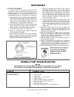
Relief Valve Adjustment Procedure:
1.
To INCREASE the pressure setting
, remove the relief
valve cap (1), loosen the locknut (3), and turn the adjusting
screw (2) inward, or CLOCKWISE.
2.
To DECREASE the pressure setting
, remove the relief
valve cap (1), loosen the locknut (3), and turn the adjusting
screw (2) outward, or COUNTERCLOCKWISE.
Refer to corresponding Blackmer pump Parts List for
relief valve spring pressure ranges.
OPERATION WITHOUT SHAFT
PROTECTOR IN PLACE CAN CAUSE
SERIOUS PERSONAL INJURY,
PROPERTY DAMAGE, OR DEATH.
Hazardous
machinery can
cause serious
personal injury.


