NOTICE:
THIS PUMP CONTAINS SOME RESIDUAL TEST FLUID
AND RUST INHIBITOR. IF NECESSARY, FLUSH PUMP
PRIOR TO USE.
Hazardous voltage.
Can shock, burn
or cause death.
Install, ground and wire to local and
National Electrical Code requirements.
Install an all-leg disconnect switch near
the unit motor.
Disconnect and lockout electrical power
before installation or service.
Electrical supply MUST match motor nameplate
specifications.
Motors equipped with thermal protection automatically
disconnect motor electrical circuit when overload exists.
Motor can start unexpectedly and without warning.
NOTICE:
BLACKMER CO2 PUMPS MUST ONLY BE INSTALLED
IN SYSTEMS DESIGNED BY QUALIFIED ENGINEERING
PERSONNEL. SYSTEM DESIGN MUST CONFORM
WITH ALL APPLICABLE REGULATIONS AND CODES
AND PROVIDE WARNING OF ALL SYSTEM HAZARDS.
INSTALLATION AND OPERATION
CRL BASE MOUNTED MOTOR DRIVEN PUMPS
PRE-INSTALLATION CLEANING
Foreign matter entering the pump WILL cause extensive
damage. The supply tank and intake piping MUST be cleaned
and flushed prior to pump installation and operation.
LOCATION AND PIPING
An improperly designed piping system or improper unit
installation WILL significantly reduce pump performance and
life. Blackmer recommends the following piping system layout
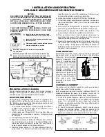
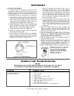
and unit installation. See Figure 2.
1. To minimize intake losses, locate the pump as close as
possible to the source of supply and a minimum of two
feet (0.6 m) below the tank outlet.
2. Intake piping and fittings MUST be at least as large in
diameter as the pump intake connection. Inlet piping must
be insulated.
3. Use high strength Schedule “80” piping.
4. Minimize the number of intake line fittings (valves, elbows,
etc.) and piping turns or bends. The nearest fitting on the
intake line must be at least 6 inches (152 mm) from the
pump to permit access to the pump relief valve .
5. Install an intake strainer 5 - 10 pipe diameters from the
pump intake. The strainer must have a net open area of at
least four times the area of the intake pipe. Strainers must
be cleaned regularly to avoid pump starvation.
6. Intake and discharge piping MUST be free of all leaks.
7. To facilitate piping expansion and contraction, expansion
joints must be placed 3 feet (0.9 m) from the pump intake
and discharge.
8. ALL piping and fittings MUST be properly supported to
prevent any piping loads from being placed on the pump.
9. Install pressure gauges in the NPT ports provided in the
pump casing to check pump performance at start up.
10. The use a vapor return line will speed up delivery by
preventing back pressure from building up at the receiving
tank and reducing pressure in the supply tank.
11. Keeping the liquefied gas systems full of liquid, even when
idle, will keep the O-rings from changing shape, shrinking
or super cooling. Evaporation of liquefied gas leaves an
abrasive powder on the surface which can cause wear to
the pump, meter, and seals.
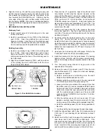
PUMP MOUNTING
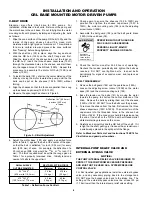
Permanently mount the unit by securing the base plate with
adequately sized anchor bolts to a level concrete floor
following recommended
industry standards (See
Figure 3). A solid foundation
will reduce system noise and
vibration, and will improve
pump performance. Refer to
ANSI/HI standards or a
suitable pump handbook for
information on typical pump
mounting and foundations.
Check coupling alignment
after pump and base
assembly is secured to the
foundation.
BOLT
BASE
STANDARD
PIPE
WASHER
Figure 3
BOLT
BASE
STANDARD
PIPE
WASHER
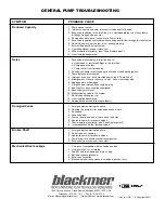
COUPLING ALIGNMENT
The pump must be directly coupled to a gear, gear reducer,
and/or driver with a flexible coupling.
Both angular and parallel coupling alignment MUST be
maintained between the pump, gear reducer, motor, etc. in
accordance with manufacturer’s instructions. See Figure 4.
1. To check for parallel alignment, the use of a dial indicator is
preferred. If a dial indicator is not available use a straight
edge. Turn both shafts by hand, checking the reading
through one complete revolution. Maximum offset must be
less than .005" (125 microns).
2. To check for angular alignment, insert a feeler gauge
between the coupling halves. Check the spacing in 90
degree increments around the coupling (four check points).
Maximum variation must not exceed .005" (125 microns).
Figure 4 - Alignment Check
3
Storage Tank
Figure 2
Unions
Bypass Valve
Gate or Ball
Valves
Intake Connection
for unloading tank
cars or tank trucks
Do no start
pump unless
this valve is
open.
Alternate
Discharge
to Storage
Tank
Discharge
Strainer


