background image

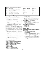
Remote Programmable Features:

Step

Function

Button 1 (Default)

Button 2

1.

Ignition Controlled Door Locks

On

Off

2.

Door Unlock Pulse

Single

Double

3.

Arming Mode

Standard

Silent

4.

Door Lock Pulse Length

.75 Seconds

3 Seconds

5.

Passive Starter Defeat Enable

Off

On

6.

Ignition Trigger  Feature

Off

On

Remote Programmable Features

To enter program mode:

1. Turn ignition to the on position.
2. Wait 2 seconds.
3. Within 10 seconds press program switch 5

times.

4. The LED and parking lights will flicker to indi-

cate the system is now in program mode.

To change programmable features:
Press program switch the number of times equal
to the feature you wish to change. The LED will
flash each time the switch is pushed. (Example:
to program feature #3 press the program switch
3 times).

• Press button 2 (Unlock) on the remote

to change the feature. The LED will flash
twice.

• Press button 1 (Lock) on the remote to

reset the feature back to default (factory) set-
ting.The LED will flash once.

System will automatically exit program mode.

Programmable Features

Program #1: Ignition Controlled Door Locks.

Button 1 = Doors lock with ignition
Button 2 = Doors do not lock with ignition

Program #2: Door Unlock Pulse

Button 1 = Single
Button 2 = Double 

Program #3: Optional Horn Mode

Button 1 = Chirp with Lock/Unlock

Button 2 = Silent

Program #4: Door Lock Pulse Length

Button 1 = 0.5 second door lock/unlock pulse
Button 2 = 3 second door lock/unlock pulse 

Program #5: Passive Starter Defeat

Button 1 = Normal
Button 2 = Starter defeat activates 45 seconds

after ignition is turned off 

Program #6: Ignition Trigger  Feature

Button 1 = Off
Button 2 = On

Default Reset

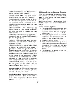
To reset all programmable features to their factory
default settings:

1. Turn ignition to the on position.
2. Wait 2 seconds.
3. Within 10 seconds press program switch 5

times. The LED and parking lights flicker to
indicate the system is now in program mode.

4. Press transmitter button 3 (Trunk). The LED

will flash 3 times, pause then continue flashing.
All programmable features will be reset to
the default position.

3

Содержание BW 852

Страница 1: ...ble to increase the range of the remote transmitters When running the harness wires through the vehicle be careful to run them where they cannot be damaged or shorted Keep them away from any moving parts or areas of high heat Use rubber or plastic grommets to protect the harness wires where they pass through holes in metal panels Main Harness BLACK WIRE Ground input Connect to a solid chassis grou...

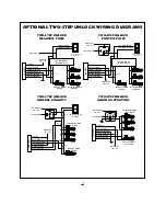
Страница 2: ...ep Unlock Diagrams YELLOWWIRE Ignition input Connect to the main ignition wire that switches 12V and does not drop out during cranking 2 Pin Red Connector Plug in connector port for LED Mount LED in an area where it may be easily seen from either side of the vehicle 2 Pin Blue Connector Plug in connector port for program service switch Mount program switch in an area that is easily accessible from...

Страница 3: ...back to default factory set ting The LED will flash once System will automatically exit program mode Programmable Features Program 1 Ignition Controlled Door Locks Button 1 Doors lock with ignition Button 2 Doors do not lock with ignition Program 2 Door Unlock Pulse Button 1 Single Button 2 Double Program 3 Optional Horn Mode Button 1 Chirp with Lock Unlock Button 2 Silent Program 4 Door Lock Puls...

Страница 4: ...tive Bad connection on WHITE wire or the output polarity is wrong for the circuit being driven Wrong door lock polarity Wrong lock wires connected Dome light relay not installed Wrong polarity selected Suggested Correction RED wire should connect direct ly to the battery Connect YEL LOW wire to true ignition wire NOT AT FUSE BLOCK Perform Code Learning sequence faster Replace remote transmitter or...

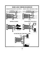
Страница 5: ...87 N O UNLOCK INPUT 30 COMMON UNLOCK OUTPUT 87A N C UNLOCK OUTPUT 87 N O LOCK INPUT 30 COMMON LOCK OUTPUT 87A N C LOCK OUTPUT STARTER DEFEAT OUTPUT 500mA DOME LIGHT OUTPUT 500mA TRUNK OUTPUT 500mA HORN HONK OUTPUT 500mA PASSENGER UNLOCK OUTPUT 500mA IGNITION INPUT WIRING HARNESS BLUE CONNECTOR RED CONNECTOR 10A FUSE 10A FUSE LED VALET SWITCH 15A FUSE 10A FUSE KEYLESS ENTRY WIRING DIAGRAM ...

Страница 6: ...LET BLUE BLACK BROWN BLACK VIOLET BLACK GREEN BLACK WHITE BLACK CONNECT TO 12V AFTER MARKET ACTUATORS HARNESS VACUUM PUMP LOCK UNLOCK SWITCH VIOLET BLUE BLACK BROWN BLACK VIOLET BLACK GREEN BLACK WHITE BLACK CONNECT TO 12V CUT X L UL HARNESS VIOLET BLUE BLACK BROWN BLACK VIOLET BLACK GREEN BLACK WHITE BLACK CONNECT TO 12V LOCK UNLOCK SWITCH CUT FACTORY DOOR MOTOR CUT X X L UL HARNESS NEGATIVE PULS...

Страница 7: ...SS BLUE WHITE FACTORY DOOR LOCK MODULE 86 30 87 87a 85 VIOLET BLUE BLACK BROWN BLACK VIOLET BLACK GREEN BLACK WHITE BLACK CONNECT TO 12V DRIVER S DOOR MOTOR PASSENGER DOOR MOTORS CUT CUT X X CUT X LOCK UNLOCK SWITCH HARNESS BLUE WHITE CONNECT TO 12V L UL 86 30 87 87a 85 VIOLET BLUE BLACK BROWN BLACK VIOLET BLACK GREEN BLACK WHITE BLACK CONNECT TO 12V DRIVER S DOOR ACTUATOR HARNESS 86 30 87 87a 85 ...

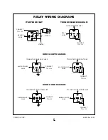
Страница 8: ...WIRE TO NEGATIVE DOME LIGHT WIRE BLACK YELLOW WIRE TO POSITIVE DOME LIGHT WIRE CONNECT TO 12V CONNECT TO 12V 86 30 87 87a 85 86 30 87 87a 85 BROWN WHITE WIRE TO NEGATIVE HORN HONK WIRE BROWN WHITE WIRE TO POSITIVE HORN HONK WIRE CONNECT TO 12V CONNECT TO 12V 86 30 87 87a 85 86 30 87 87a 85 STARTER DEFEAT TRUNK RELEASE DIAGRAM DOME LIGHT DIAGRAM HORN HONK DIAGRAM RELAY WIRING DIAGRAMS ...

Отзывы: