background image

5

High Performance 700TVL CCTV Dome Camera User Manual

SECTION 2: INSTALLATION

1. 

Remove the camera dome cover from the camera. If you have a BLK-CPD700 series camera, use a coin to pry off the cover. For 
BLK-CPV cameras, loosen the four captive dome screws using the Torx L-wrench provided.

2. 

Remove the camera module from the base by loosing the three captive screws that secure the camera module to the base.   

3. 

Determine (and acquire, if needed) the best type of fasteners for attaching the camera to the mounting surface. The 
mounting screws and wall inserts provided are adequate for most surfaces. 

4. 

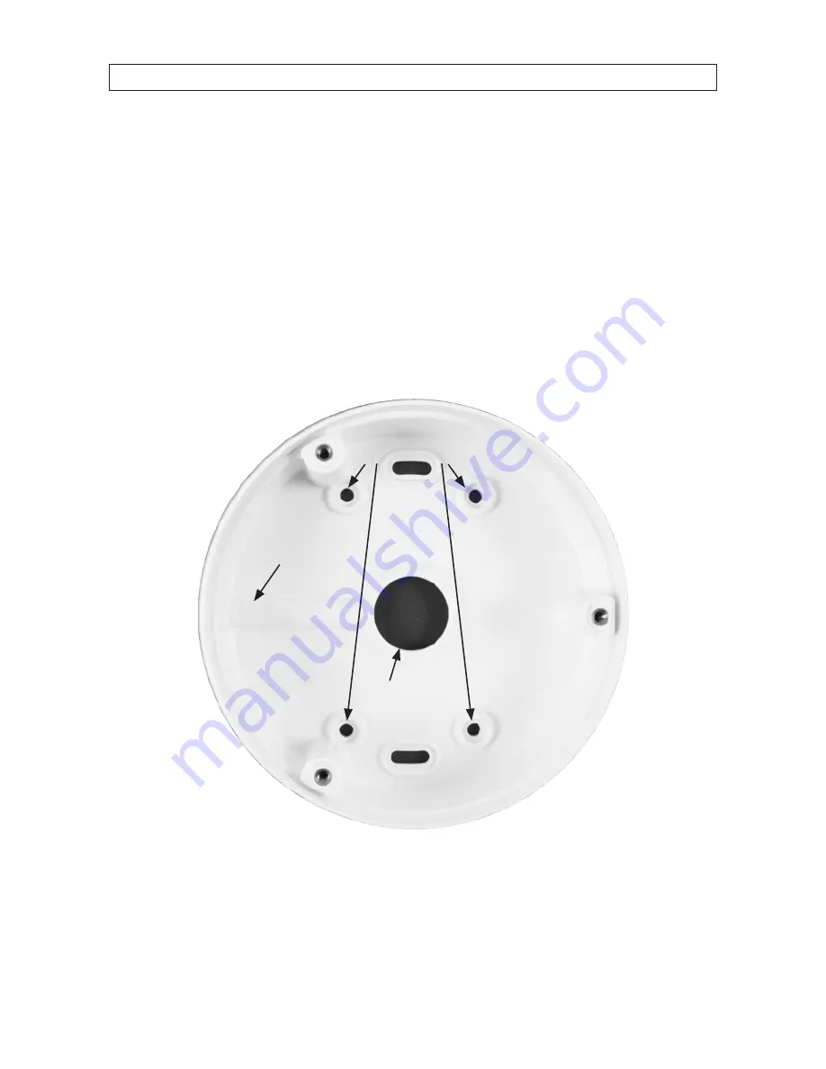
Using the camera base as a guide, mark the location of the screws that anchor the base to the mounting surface. For 
mounting the camera to a surface, mark the four screw locations four holes. See the photo below. If you are routing the drop 
cable through the hole in the base and then through the mounting surface, also mark the position of the hole in the center of 
the base for the drop cable. 

Screw locations for 

surface mount

Hole in 

base for 

drop cable 

(conduit) 

Cable channel  

(between base and surface)

BLK-CPD700 series camera base 

Содержание BLK-CPD700

Страница 1: ...User Manual Products BLK CPD700 BLK CPD700R BLK CPV700 BLK CPV700R BLK CPD700andBLK CPV700R Please read this manual before using your camera and always follow the instructions for safety and proper us...

Страница 2: ...Observint Technologies Observint products are designed to meet safety and performance standards with the use of specific Observint authorized accessories Observint disclaims liability associated with...

Страница 3: ...2 2 Mounting the camera 4 2 2 1 Mounting the camera onto a surface 4 2 2 2 Installing the camera with a mounting bracket 7 2 3 Camera FOV adjustments 9 SECTION 3 Software Setup 11 3 1 LENS 11 3 2 EXP...

Страница 4: ...gh Very high humidity levels can reduce image quality Do not install the camera under unstable lighting conditions Severe lighting change or flicker can cause the camera to work improperly Do not touc...

Страница 5: ...CPV700 BLK CPV700R only Smart IR produces vivid images in total darkness True Day Night with ICR BLK CPD700R BLK CPV700R only Smart 3DNR prevents image blurring of moving object Activates only if mov...

Страница 6: ...erts to secure the base to the mounting surface Torx T 20 L wrench for removing the dome BLK CPV700 series only Power adapter cable with female plug for power drop cable Video test port to BNC adapter...

Страница 7: ...ser Manual 1 1 3 Optional mounting brackets Two optional mounting brackets are available for the BLK CP700 series cameras BLK WALLMT Wall mount bracket BLK PENDMT Pendant mount bracket BLK WALLMTbrack...

Страница 8: ...A adapter or 12 Vdc power source DC12V 1A adapter When connecting 12 Vdc power to the camera power drop observe the polarity shown on the terminal block Video coax connector BNC yellow sleeve for tran...

Страница 9: ...eners for attaching the camera to the mounting surface The mounting screws and wall inserts provided are adequate for most surfaces 4 Using the camera base as a guide mark the location of the screws t...

Страница 10: ...e more appropriate 6 Drill a 3 4 hole through the mounting surface for the drop cable if necessary 7 Route the camera drop cable through the base as planned 8 If you are installing a BLK CPV700 series...

Страница 11: ...12 Vdc or 24 Vac power source 14 Apply power to the camera Verify that video from the camera can be seen on the video monitor 2 2 2 Installing the camera with a mounting bracket The BLK CPD700 series...

Страница 12: ...ng bracket with the camera to the bracket mounting plate after routing the end of camera drop cable appropriately Use the four screws provided with the bracket 10 Connect the camera drop cable video a...

Страница 13: ...y watching video with a setup monitor attached to the video test port on the OSD control board NOTE A video test port to BNC adapter cable is provided Video test port OSDcontrolboard 2 Pan adjustment...

Страница 14: ...lace Tilt adjustment image up or down Pan adjustment image left or right 3 Tilt adjustment moves video up or down Rotate the camera about the gimbal axis to center your surveillance target in the vide...

Страница 15: ...e SETUP joy stick on the OSD control panel to navigate through the menu system Press the joy stick in toward the control board to open the SETUP menu or select an entry rock the stick up or down to hi...

Страница 16: ...en press the joy stick in The EXPOSURE sub menu will open SHUTTER This function is used to select automatic AUTO shutter speed control or set the shutter speed manually SHUTTER speed can between 1 60...

Страница 17: ...N and press the joystick in to save changes and return to the EXPOSURE menu BLC Back Light Compensation This feature enables the camera to compensate for strong back light conditions in a selected are...

Страница 18: ...efault AREA position and size RETURN Select RETURN to return to the EXPOSURE submenu HSBLC Highlight Suppression Back Light Compensation The HSBLC feature enables you to suppress specific areas of the...

Страница 19: ...th default LOW LEVEL and HIGH LEVEL settings for normal outdoor lighting condition These settings can be adjusted in the OUTDOOR sub menu RETURN Select RET to return to the EXPOSURE menu RETURN In the...

Страница 20: ...left to Increase or decrease the value of BLUE B gain or RED R gain while monitoring the color of the image Select RETURN to go to the SETUP menu NOTE The White Balancemaynotbeworkedproperlyinthefollo...

Страница 21: ...stance IR SMART is applied to objects in a specified area of the image IRSMARToff IRSMARTon Selecting IR SMART ON opens the IR SMART sub menu where you can set the IR gain and position and size of the...

Страница 22: ...he picture is displayed in color AUTO In this mode the camera automatically switches to COLOR in normal condition and to B W mode when ambient illumination is low Selecting this option opens the AUTO...

Страница 23: ...ncrease the level of noise reduction The default setting is 200 maximum RETURN Select RET to return to the SETUP menu or END to close the SETUP menu 3 6 SPECIAL Selecting SPECIAL opens a feature list...

Страница 24: ...character array before the 0 top line leftmost position and press the joystick in to select it blank character To clear all entries in the title highlight CLR then press the joystick in To position t...

Страница 25: ...t D ZOOM then rock the joystick right to set the RANGE magnification Similarly adjust the PAN and TILT options to move to the portion of the image you want to magnify RETURN Select RETURN to return to...

Страница 26: ...TION display rock the joystick left right up and or down to move the block detection area to the region of the display you want to monitor then press the joystick in to select that position and move t...

Страница 27: ...acy area rock the joystick up down left or right to reposition the corner of the shape you want to move Press the joystick in to move to another corner of the image then advance to the POSITION displa...

Страница 28: ...oystick in to open the DEFOG MANUAL submenu LEVEL Rock the joystick left or right to select the level of the DEFOG function 0 31 High level numbers apply more filtering COLOR GAIN Sets the color level...

Страница 29: ...onitor type you using LCD or CRT or select USER The monitor feature enables you to setup your camera to produce the best image for the monitor you use Rock the joystick left or right to select either...

Страница 30: ...26 SECTION 3 SOFTWARE SETUP FACTORY Select FACTORY to reset the camera configuration RETURN Rock the joystick to select RETURN to return to the SETUP menu 3 9 EXIT Select EXIT to close the SETUP menu...

Страница 31: ...gently rub the surface with a soft cloth moistened with a mild detergent solution then rinse and dry it with a soft cloth Remove all foreign particles such as plastic or rubber materials attached to t...

Страница 32: ...00001 Lux Sens up 256 0 Lux IR LED on 0 00001 Lux Sens up 256 0 Lux IR LED on White Balance ATW AWB Manual AWC SET Electronic Shutter Speed AUTO 1 50 sec 1 60 sec 1 100 000 sec Sense Up Off Auto x2 x2...

Страница 33: ...iris varifocal lens 2 8 12 mm Operational Temperature 14 F 122 F 10 C 50 C RH 95 max Storage Temperature 4 F 142 F 20 C 60 C RH 95 Max Dimension W x H x D 5 91 x 4 72 x 5 91 150 mm x 120 mm x 150 mm...

Страница 34: ...setting of the MD AREA The image on the monitor flickers Make sure that the camera isn t facing direct sunlight or fluorescent light If necessary change the camera position Colors are not quite right...

Страница 35: ...High Performance 700TVL CCTV Dome Camera User Manual APPENDIX B CAMERA DIMENSIONS APPENDIX B Camera Dimensions BLK CPD700 shown BLK CPD700R 5 91 in 4 72 in BLK CPV700 BLK CPV700R shown 5 91 in 4 80 i...

Отзывы: