


4
®
1
ON
4
2
3
5V
1A
Pan-head
screw
Countersunk
screws x 2
Rack
securing
plate
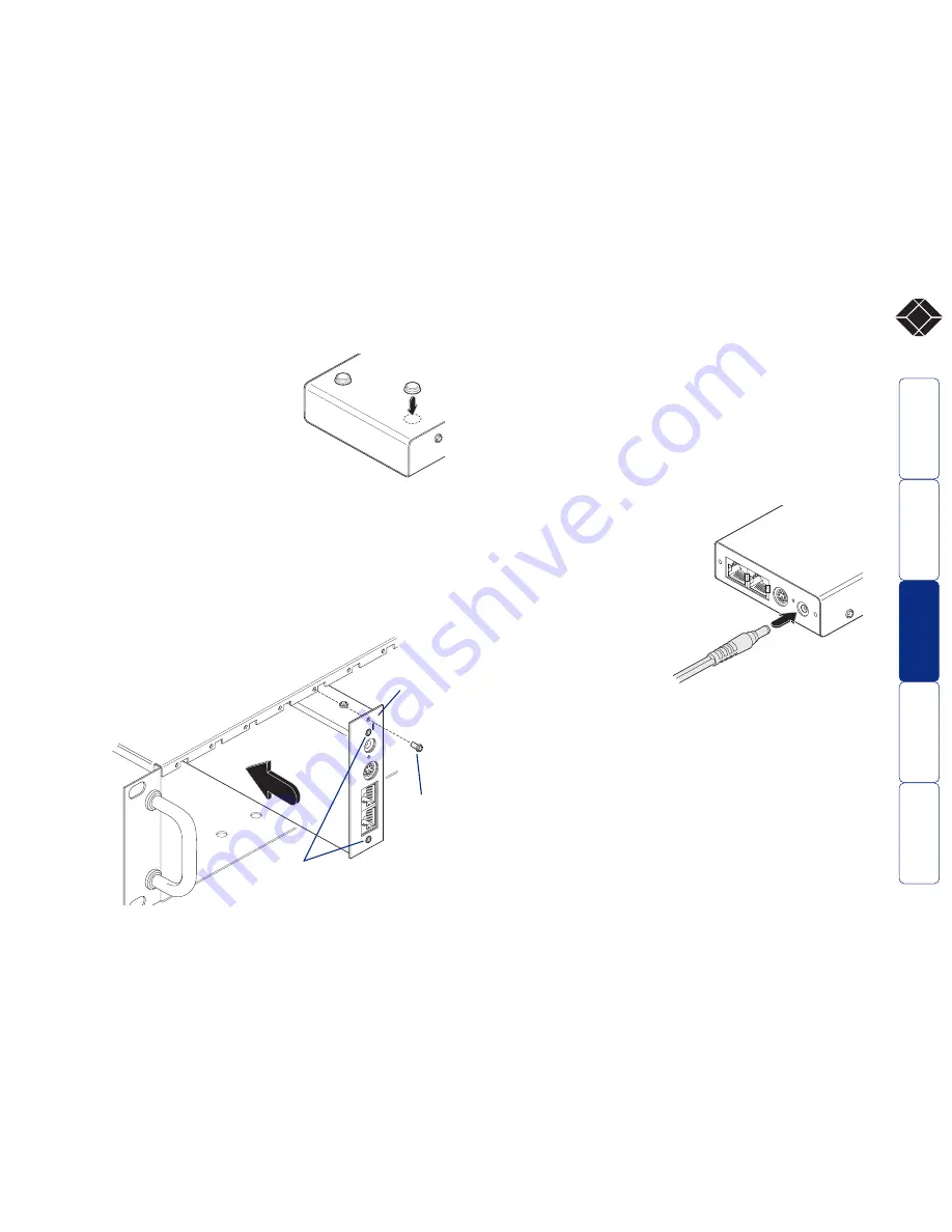
Stage B - Mounting the module – desk or rack
The Wizard Extender ACU5013A can be situated on a desk (or floor) or
alternatively, for larger installations, mounted within an optional rack
mount chassis.
Desk mount
Apply the supplied self-adhesive rubber
feet to the underside of the module.
Rack mount
Note: The module switches are not accessible
once it is inserted into the rack, therefore, check all
settings before insertion.
1 Place the rack securing plate (available as a separate kit) onto the
front of the module and secure it with the two countersunk screws.
2 Orient the Wizard Extender ACU5013A module on its side so that
its labelled face is the correct way up and the two blue video
connectors are facing into the rack.
3 Slide the module into the required rack position. The rectangular
cut-out in the front upper lip of the rack allows the two screws on
the module’s upper edge to slide through.
4 The rack mount chassis has a series of holes in its floor that are
spaced to accommodate the two screws on the
module’s lower edge. Ensure that the screws
correctly locate into the two holes of the
chosen slot. The rack securing plate
on the module should now be
flush with the front of the
rack mount chassis.
Stage C – Connections
Most connections to the Wizard Extender ACU5013A are common to
both of the operational modes, while other connections differ
depending on whether the ‘Two-in, two-out’ or ‘One-in, two-out’
modes are selected.
Connections at the Wizard Extender ACU5013A
Power connection
The Wizard Extender ACU5013A can obtain its power perfectly well
from its keyboard connection to the computer system. Thus, if the
keyboard connection is made to the computer, the power adapter is
not necessary. If, however, the Wizard Extender ACU5013A will not use
a keyboard connection, then the power supply must be used:
1 Attach the output connector of the
power supply to the socket at the
front edge of the module labelled
POWER.
2 Insert the IEC connector of the
supplied power lead into the
corresponding socket of the power
supply. Connect the other end of
the power lead to a nearby mains
socket.
When power is applied, either
via the keyboard connector or
power supply, the small
indicator situated on the front edge of the module adjacent the POWER
socket will glow red.
Note: It is also possible to supply power to the module using the
Expansion connector situated adjacent to the configuration switches.
The use of this connector is beyond the scope of this user guide.
Note: The module contains an internal automatic cut-out fuse to
protect against power surges. To reset, remove power from the module
for one second and then reconnect.
5 Use the third (pan-head) screw, in the top hole of the rack securing
plate to fasten the module to the rack.


