10
MULTIMODE FOMS -ST AND -SMA
Once you have configured each MultiMode FOM properly (see
Chapter 3
)
and installed them and their fiber and RS-232 cables (see
Chapter 4
), you are
ready to operate the units. This chapter describes how to (a) interpret the
LED indicators, (b) power the units up and down, and (c) use the built-in
loopback-test modes.
5.1 LED Indicators
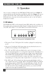
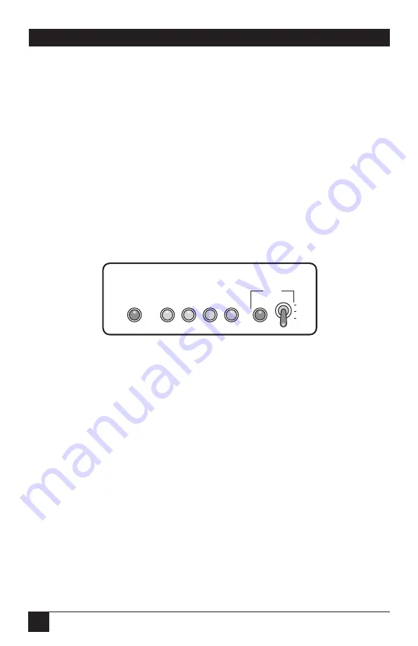
The MultiMode FOM’s six front-panel status LEDs indicate the condition of
the modem and communication link. Figure 5-1 below shows the location of
each LED; after Figure 5-1 is a description of each LED’s function.
• The green “Power” LED glows if the modem is plugged in and getting
power.
• The green “Test Modes” LED glows when the modem has been set to
perform a local analog or remote digital test.
• The “TD” and “RD” indicators blink red or green in response to data
activity (transmitting data or receiving data respectively). Red indicates a
“low” level of RS-232 logic; green indicates a “high” level of RS-232 logic.
These LEDs will continuously glow red if the RS-232 cable connections
are correct and the RS-232 device to which the FOM is attached is not
transmitting or receiving data (this is equivalent to a constant “low” state).
• The “RTS” and “CD” indicators are also tri-state and will glow red for a
“low” signal or green for a “high” signal. The RTS LED lights in response
an incoming signal on RS-232 Pin 4 (normally Ready to Send). The CD
LED lights (a) in response to an incoming Carrier Detect signal on the
line side (from the remote FOM) and (b) when, as a result, the FOM
outputs the same signal on RS-232 Pin 8.
Figure 5-1. Front panel of the MultiMode FOM.
POWER
Test
Modes
Remote
Normal
Local
TD
RD
CD
RTS
MultiMode FOM
5. Operation


