14
ACTIVE CCTV RECEIVER HUB, 16-PORT
7. Power on the CCTV cameras and the DVR. When a video signal is detected,
the green LED on each hub port will turn on.
8. Due to the hub’s automatic gain control, the camera images may take a few
seconds to stabilize. This is normal. The hub automatically adjusts the
brightness, sharpness, and color to compensate for effects due to the cabling
conditions. Use the adjustments on the CCTV camera, DVR, or monitor to
fine tune the final picture.
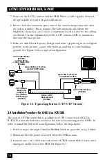
9. If there is visible low-frequency background noise (appearing as a wood-grain
pattern) in the picture, connect the hub’s ground lug to a true building
ground. See Figure 3-6 for a typical configuration.
Figure 3-6. Typical application (UTP/UTP version).
3.4 Installation Procedure for IC455A or IC455AE
The Active CCTV Receiver Hub is available in a UTP/coax version (IC455A,
IC455AE) where the hub is located near the central monitoring system (DVR). In
order to install the hub in this configuration, follow the steps below.
1. Perform steps 1 through 3 listed in
Section 3.3
, then proceed to step 2 below.
2. Make sure that the power is turned off on the DVR or mux.
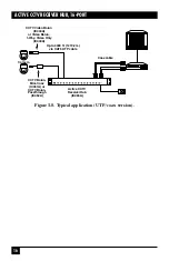
3. Connect one coax cable from each Active CCTV Receiver Hub to each video
input port on the rear of the DVR. See Figure 3-7.
CCTV Video Balun
(IC444A)
or Video Balun,
1-Way, Video Only
(IC440A)
CCTV Balun,
Mini-Coax
(IC451A) or
CCTV Balun,
Passthrough
(IC452A)
Active CCTV
Receiver Hub
(IC455A)
Up to 500 ft. (152.4 m)
via CAT5 UTP cable
Up to 4000 ft. (1219.2 m)
via CAT5 UTP cable
CCTV Video Baluns
(IC444A)
Содержание IC454A
Страница 3: ......


