background image

43

CHAPTER 5: Autotest

5.2.1 OFSTP-14A M

ETHOD

B R

EFERENCE

Method B is the recommended method for testing
multimode cable under TIA/EIA-568A and ISO/IEC
11801. This method is appropriate when measuring a
cable plant with patch panels on both ends, or with a
patch panel on one end and a wall outlet on the other.
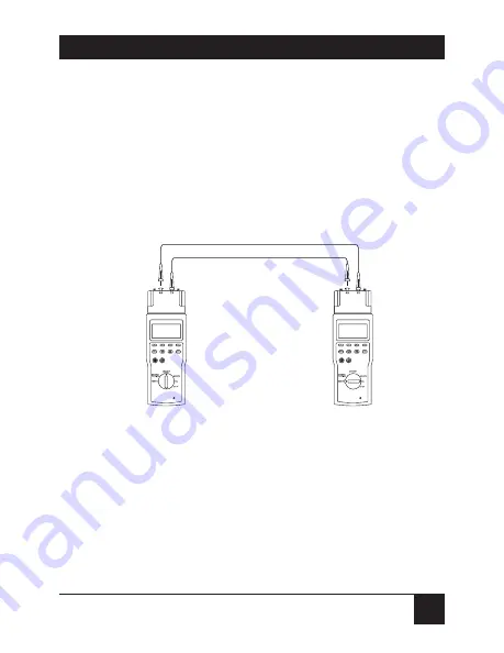
See Figure 5-1.

Figure 5-1. Setting reference per TIA/EIA-526-14A (OFSTP-14A),

Method B.

To set the Method B reference:

1. Attach the test jumpers to connect the Main Unit

and Remote Unit as shown in Figure 5-1.

2. Turn the rotary dial on the Main Unit to 

CAL

.

Main Unit

Remote Unit

Test Jumper A (850/1300 nm)

Test Jumper B (850/1300 nm)

Содержание Fiber Meter

Страница 1: ...1000 Park Drive Lawrence PA 15055 1018 724 746 5500 Fax 724 746 0746 Copyright 2003 Black Box Corporation All rights reserved...

Страница 2: ...n the U S Call 877 877 BBOX outside U S call 724 746 5500 FREE technical support 24 hours a day 7 days a week Call 724 746 5500 or fax 724 746 0746 Mailing address Black Box Corporation 1000 Park Driv...

Страница 3: ......

Страница 4: ...by poor handling especially at connectors Dirt is harmful to fiberoptic connectors Clean the ends of connectors with alcohol cleaning pads before testing or reassembling equipment Do not bend fibers t...

Страница 5: ...ican Telephone and Telegraph Company Windows and Windows NT are either registered trademarks or trademarks of Microsoft Corporation in the United States and or other countries Any other trademarks men...

Страница 6: ...res 11 2 4 The Handset 13 2 5 Battery Information 15 2 5 1 Low Battery Message 16 2 5 2 Changing the Batteries 16 2 5 3 Recharging the NiMH Battery Pack 17 2 6 Changing Performance Modules 18 3 Setup...

Страница 7: ...11 Set the Date 30 3 12 Set the Time 30 3 13 Set Audible Tones 31 3 14 Set the Circuit Names 32 3 15 Set the Company Name 34 3 16 Reset to Defaults 35 4 Calibration 37 5 Autotest 40 5 1 Set the Loss...

Страница 8: ...me 60 6 Extended Functions 61 6 1 LinkTalk 61 6 2 Manual Power Meter 63 6 3 Manual LED Source 68 6 4 Manual Multimode Loopback Measurements 69 6 5 Self Test 72 6 6 Download Firmware 72 6 7 Upload Repo...

Страница 9: ...us 84 A 2 2 Toolbar 85 A 2 3 Status Bar 86 A 2 4 Help 86 A 3 Setting Up Report Manager 87 A 3 1 Detecting the COM Port 87 A 3 2 Connecting the Fiber Meter to a PC 88 A 4 Using Report Manager 89 A 4 1...

Страница 10: ...1 Backbone Equation 3 Equation 4 N A 90 m 62 5 m and 50 m 1000BASE SX 62 5 m 2 53 dB N A N A 275 m 1000BASE SX 50 m 3 43 dB N A N A 550 m 1000BASE LX N A 2 32 dB N A 550 m Equation 1 Max Loss of mated...

Страница 11: ...1001 to 6600 ft 305 1 to 2011 7 m 2 ft 0 6 m 3 IOR uncertainty Multimode Propagation Delay Range 10 to 10 000 ns Multimode Loss Dynamic Range 3 dBm to 50 dBm Resolution 0 01 dB dBm Accuracy 0 3 dB 20...

Страница 12: ...OTEST EXTENDED FUNCTIONS and REMOTE Operating Humidity 10 to 90 noncondensing Temperature Range Operating 32 to 122 F 0 to 50 C Storage 4 to 140 F 20 to 60 C Power Source per handset Batteries 8 AA al...

Страница 13: ...It also provides pass fail results The Fiber Meter uses an automated link loss budget calculation as part of the pass fail determination The Fiber Meter can store up 2000 Autotest records 1000 in each...

Страница 14: ...or damaged contact Black Box at 724 746 5500 2 3 Features Tests two multimode fibers with one setup Measures bi directional loss at 850 nm and 1300 nm simultaneously Calculates the link loss budget M...

Страница 15: ...12 FIBER METER Determines margin beyond pass fail limits Stores up to 2000 Autotest reports Uploads test reports to a PC for archiving and printing Contains a built in audio communication system...

Страница 16: ...screen The up and down arrows scroll through menus and screens The Enter key accepts the highlighted selection Power Powers the Fiber Meter on and off Backlighting Adjusts the backlighting for the dis...

Страница 17: ...the cable index of refraction IOR and sets the Autotest reference power SETUP Defines each of the basic operational settings for the Fiber Meter including Test Mode Number of Connections Number of Spl...

Страница 18: ...ONS LinkTalk Manual Power Meter mode Manual LED Source mode Manual Multimode Loopback Measurements Self Test Download Firmware Upload Reports 2 5 Battery Information Each Fiber Meter handset is shippe...

Страница 19: ...life lithium cell This cell permits stored test results and setup conditions to remain saved in non volatile memory when you replace the AA alkaline batteries or rechargeable battery pack The lithium...

Страница 20: ...talling new batteries 4 Press the Power button to continue regular operations 2 5 3 RECHARGING THE NIMH BATTERY PACK When the AC mains adapter is used and the Fiber Meter is powered off the tester goe...

Страница 21: ...ce Modules Each Fiber Meter handset comes with a fiberoptic performance module that attaches to the top of the unit The fiberoptic performance module contains much of the key optical measurement circu...

Страница 22: ...he screws are free of the retainer 2 Grip the performance module on either side and slide the module out of the handset To install a performance module 1 Slide the performance module into the handset...

Страница 23: ...it To designate the second handset as the Remote Unit set the Rotary Dial to REMOTE Before you begin a fiber certification test set the Main Unit to the specific configuration you want to use Many of...

Страница 24: ...r 62 5 m 62 5 m Units F4 to toggle between Feet Feet and Meters PowerDown F2 to decrease time until 30 min 2 to 30 minutes power down or disabled F3 to increase time until power down Backlighting F2 t...

Страница 25: ...hour hh mm ss F3 to change the minute F4 to change the seconds to zero Audible Tones F4 to toggle between On on or off enabling and disabling tones Circuit Names F1 for None Next F2 for Blank F3 for...

Страница 26: ...loss measurements are made on each fiber in one direction one way testing see Figure 3 1 or on each fiber in both directions two way testing see Figure 3 2 When running Autotests one handset is used a...

Страница 27: ...Press the up and down arrow buttons until Test Mode is highlighted 3 Press the F4 button to toggle between OneWay and TwoWay 3 2 Set the Number of Connections IMPORTANT Specifying the number of fiber...

Страница 28: ...tions Press the F3 button to increase the number of connections 3 3 Set the Number of Splices 1 Set the rotary dial on the Main Unit to SETUP 2 Press the up and down arrow keys until Of Splices is hig...

Страница 29: ...Measurement Units 1 Set the rotary dial on the Main Unit to SETUP 2 Press the up and down arrow keys until Units is highlighted 3 Press the F4 button to toggle between Feet and Meters 3 6 Set the Pow...

Страница 30: ...ess the F3 button to increase the amount of time until power down To disable PowerDown 1 Set the rotary dial on the Main Unit to SETUP 2 Press the up and down arrow keys until PowerDown is highlighted...

Страница 31: ...ount of time the backlighting stays on 3 8 Set the Power Frequency Power Frequency sets the Fiber Meter with the frequency of the local AC mains power Setting the Power Frequency properly avoids displ...

Страница 32: ...t to SETUP 2 Press the up and down arrow keys until Baud Rate is highlighted 3 Press the F2 button to decrease the baud rate 4 Press the F3 button to increase the baud rate 3 10 Set the Flow Control F...

Страница 33: ...ailable date formats mm dd yy default dd mm yy or yy mm dd 1 Set the rotary dial on the Main Unit to SETUP 2 Press the up and down arrow keys until Date is highlighted 3 Press the F1 button to change...

Страница 34: ...ss the F4 button to set the seconds to zero 3 13 Set Audible Tones Use this parameter to enable audible tones at the end of tests A different audible tone is created for the pass fail test results 1 S...

Страница 35: ...n Unit to SETUP 2 Press the up and down arrow keys until Circuit Names is highlighted 3 Press the F1 button to select NONE the F2 button to select BLANK the F3 button to select NEXT and the F4 button...

Страница 36: ...last ID ends in a B the next ID will end in a C and so on Numbers used can be 0 through 9 and letters used can be A through Z SAME You can enter the Circuit ID that s the same as the last ID used NOTE...

Страница 37: ...he rotary dial on the Main Unit to SETUP 2 Press the up and down arrow keys until Company Name is highlighted 3 Press the F4 button or the ENTER button to modify the name Figure 3 5 Selecting the comp...

Страница 38: ...ccelerate scrolling of characters Press the ENTER button to save the new name 3 16 Reset to Defaults Reset to Defaults allows you to return the Fiber Meter s internal settings to their factory default...

Страница 39: ...e defined in Table 3 1 at the beginning of this chapter 4 Press the F3 button to reset the IOR Index of Refraction value to its default value of 1 490 NOTE Index of refraction IOR is a measure of the...

Страница 40: ...speed of light through a fiber Setting the appropriate IOR value is important to making accurate multimode fiber length measurements You can set the IOR as follows Use the system default IOR setting...

Страница 41: ...F4 button to calibrate IOR Figure 4 1 appears Figure 4 1 Setting IOR 4 Select one of the following responses Press the F4 button to use the default setting Press the F2 button to manually change the I...

Страница 42: ...39 CHAPTER 4 Calibration 5 Press the ENTER button to save the new IOR setting 6 Press the ESC button to return to the CALIBRATE menu...

Страница 43: ...roles of the two Fiber Meter handsets can be reversed to use the report storage capability of both handsets An Autotest requires you to perform the following steps Set the loss budget see Section 5 1...

Страница 44: ...uired to set the Autotest reference power before testing Setting the reference stores the loss from the test jumpers launch cables and subtracts this loss from the measured values using the cable unde...

Страница 45: ...icant change in temperature since the reference was last established If the Fiber Meter is used over long intervals of time you should re establish the reference every couple of hours to allow for cha...

Страница 46: ...h patch panels on both ends or with a patch panel on one end and a wall outlet on the other See Figure 5 1 Figure 5 1 Setting reference per TIA EIA 526 14A OFSTP 14A Method B To set the Method B refer...

Страница 47: ...igure 5 2 Figure 5 2 Highlighting Set Reference 4 Press the F4 button to calibrate When you finish setting the power reference a message confirms that the references were set This message is followed...

Страница 48: ...power references in the Remote handset separately To do this turn the rotary dial on the Fiber Meter Main Unit to REMOTE turn the dial on the Remote Unit to CAL and repeat the reference setting proced...

Страница 49: ...ure 5 4 Setting reference per TIA EIA 526 14A OFSTP 14A Method A 2 Turn the rotary dial on the Main Unit to CAL 3 Press the up and down arrow keys until Set Reference is highlighted 4 Press the F4 but...

Страница 50: ...set ignore this message Press the F4 button to acknowledge the message NOTE If you expect to change the operation roles of the Fiber Meter handsets for example to initiate tests from either end of the...

Страница 51: ...r the reference has been set After you set the reference you are ready to make Autotest measurements Connect the two handsets the test jumpers and the installed fiberoptic cable as shown in Figures 5...

Страница 52: ...ys the optical power measured at the receiving end of both cables see Figure 5 8 RX Results for the cable connected to the Main Unit s RX port TX Results for the cable connected to the Main Unit s TX...

Страница 53: ...t Optical Power Measurements display screen see Figure 5 8 press the F2 button on the Main Unit to start Autotest loss measurements The Autotest Summary screen is displayed at the completion of the Au...

Страница 54: ...nected to the Main Unit s TX port This screen also shows the measured length and propagation delay See Figure 5 10 Figure 5 10 Autotest TX Loss screen 2 Press the F1 button to display the Autotest RX...

Страница 55: ...or RX Loss screen press the F2 button to display the Autotest Margin Screen see Figure 5 12 This screen shows the amount of headroom between the loss budget and the measured loss Figure 5 12 Autotest...

Страница 56: ...emote Unit are properly connected to test jumpers and to the cable under test To do that check the following Verify that the RX port on the Main Unit is connected through the cable to the TX port on t...

Страница 57: ...essage on the Autotest Summary screen will prompt you to swap the connections when the first step of the Autotest is completed See Figure 5 13 Figure 5 13 Autotest Summary screen 2 Swap the cables and...

Страница 58: ...during the first step of the Autotest Loss results are displayed in both the Main to Remote and Remote to Main directions This screen also shows the measured length and propagation delay See Figure 5...

Страница 59: ...t of the Autotest 5 6 Changing The Cable Test Standard You can select or change the cable test standard that the Fiber Meter uses for Autotest pass fail determinations The currently selected cable tes...

Страница 60: ...esults can later be uploaded to a PC or printer See Chapter 7 for a description of how to output test results Since Autotest performs measurements on two separate fiberoptic cables you must assign a c...

Страница 61: ...NTER button on the Autotest Summary screen any Autotest Loss screen or any Margin screen The Fiber Meter automatically assigns a sequential report number You can press the up and down arrows keys to c...

Страница 62: ...cond report to the same number as a previous report erasing the earlier one Figure 5 18 Warning on use of same report number After saving a message in the upper right of the screen displays the report...

Страница 63: ...has already been assigned to another stored report will cause the following warning to appear Circuit ID Not Unique Figure 5 19 Assignment of circuit ID To enter the next circuit identifier 1 Press th...

Страница 64: ...ted using a pair of multimode fibers with one handset set to REMOTE and the other operating in EXTENDED FUNCTIONS as shown on the following pages LinkTalk can be activated following any Autotest even...

Страница 65: ...the Main Unit and Remote Unit 3 Set the rotary dial on the Main Unit to EXTENDED FUNCTIONS 4 Press the up and down arrow keys to highlight LinkTalk 5 Press the ENTER button When the Remote Unit enter...

Страница 66: ...ual optical power meter for measuring optical power and loss of multimode fiber at either an 850 nm or 1300 nm wavelength Connections are made to the RX port You can use the other Fiber Meter handset...

Страница 67: ...ecked to ensure that they have not become worn through and are not adding excessive loss Always clean the connector ferrules before making connections Figure 6 2 Setting the manual power meter referen...

Страница 68: ...ween 850 and 1300 nm wavelengths see Figure 6 3 Figure 6 3 Manual Power Meter mode 5 Set Fiber Meter Unit B to EXTENDED FUNCTIONS select LED Source then press the F3 button which toggles between 850 a...

Страница 69: ...n optical reference The Manual Power Meter reference is only retained while the unit is in the Manual Power Meter mode Setting a Manual Power Meter reference does not change an Autotest reference set...

Страница 70: ...ber Meter Power Meter CAUTION Once the reference measurement has been made and you are ready to begin testing do not disconnect the test jumper from the optical source TX port of the Fiber Meter hands...

Страница 71: ...3 Manual LED Source The Manual LED Source function allows either Fiber Meter handset to function as a manual optical light source at either 850 nm or 1300 nm wavelengths This capability is particularl...

Страница 72: ...eter handset can be used as a loss test set to test single multimode cables including patch cords 1 Set the rotary dial on the Main Unit to EXTENDED FUNCTIONS 2 Press the up and down arrow keys until...

Страница 73: ...nual Multimode Loopback mode 5 Press the F3 button to set 850 nm as the wavelength 6 Press the F4 button to set the 850 nm reference 7 Press the F3 button to select the 1300 nm wavelength 8 Press the...

Страница 74: ...oss measurements will be displayed Figure 6 7 Making loss measurements in Manual Loopback mode NOTE Do not remove the test jumper from the Fiber Meter TX port after the reference is set 10 To obtain t...

Страница 75: ...d 3 Press the ENTER key The test begins immediately and the display screen shows the test results If the self test fails make a note of which test failed and contact Black Box Technical Support at 724...

Страница 76: ...viewing or printing and you can load several report files at the same time Loaded files cannot be altered by the Report Manager 7 1 View Test Reports The Fiber Meter allows you to view test reports b...

Страница 77: ...from the Fiber Meter handset to a serial printer only Contact Technical Support at 724 746 5500 for details CAUTION The PC interface cable supplied with the Fiber Meter may not connect properly to al...

Страница 78: ...highlighted See Figure 7 1 Figure 7 1 Results menu Test 0002 selected To print a selection of reports press the up and down arrow keys until the number of each test report you want to print is highli...

Страница 79: ...All tests selected from the RESULTS menu NOTE Reports can be de selected by highlighting a selected report and pressing the F1 button prior to printing 3 Press the F4 button or the ENTER button to pr...

Страница 80: ...s 0 Core Diameter 62 5 Length PASS Measured Length Limit Delay 322 ft 6560 ft 488 ns Optical Loss PASS Direction Main Remote Wavelength Loss dB Limit dB Margin dB Status 850 nm 0 45 dB 1 87 dB 1 42 dB...

Страница 81: ...plices 0 Core Diameter 62 5 Length PASS Measured Length Limit Delay 322 ft 6560 ft 488 ns Optical Loss PASS Direction Main Remote Wavelength Loss dB Limit dB Margin dB Status 850 nm 0 45 dB 1 87 dB 1...

Страница 82: ...lete is highlighted Then press the F1 button To delete a selection of reports press the up and down arrow keys until the number of each test report you want to delete is highlighted Press the F1 butto...

Страница 83: ...he deletion press the F1 button or the ESC button This takes you back to the RESULTS menu 7 5 Change Serial Port Settings The RESULTS function allows you to adjust the following serial port settings B...

Страница 84: ...cific instructions 3 Press the F4 button 4 Press the F1 button to increase the baud rate from 1200 bps to up to 38 400 bps 5 Press the F2 button to select the flow control XON XOFF software HARDWARE C...

Страница 85: ...82 FIBER METER 7 Press the F4 button to print the reports Serial port settings changes are automatically stored in non volatile memory NOTE To abort a report printout press the ESC button...

Страница 86: ...protected from tampering encrypted and compressed format or in a text format for use by another program Report Manager allows you to print the reports with optional headers and footers A 1 Installatio...

Страница 87: ...to find and run the Report Manager Setup program A 2 Report Manager Components Report Manager components include Menus Toolbar Status Bar Help A 2 1 MENUS All Report Manager functions can be accessed...

Страница 88: ...OOLBAR Toolbar buttons see Figure A 2 provide quick access to these commonly used functions Open file Save file Print reports Upload reports Help The Toolbar can be enabled or disabled from the View m...

Страница 89: ...tions can be changed from the View menu A 2 4 HELP For help on any menu command Toolbar button or other Report Manager item click on the What s This Help button or press Shift F1 the mouse pointer cha...

Страница 90: ...e unable to properly respond to the automatic searches by Report Manager When this occurs the PC can slow down or exhibit erratic mouse operation If your COM port is not being detected automatically y...

Страница 91: ...the standard serial interface null modem cable to an available PC COM port on the Fiber Meter 2 Connect the other end dual connector use either a 9 or 25 pin connector to a PC See Figure A 3 Figure A...

Страница 92: ...est reports Save test reports to disk Load test reports from disk Download firmware from the PC or Web site to the Fiber Meter A 4 1 UPLOAD TEST REPORTS You can upload Autotest results from the Fiber...

Страница 93: ...until the message Link Established is shown in the Report Manager s status bar NOTE If the status bar continues to display No Communications Link Established check the COM port settings See Section A...

Страница 94: ...ummaries shown can be restricted by selecting or deselecting options in the Display Summaries box 6 To save the summary list to a text file click Save Report List 7 To upload the reports select one of...

Страница 95: ...time required to complete the download is given below the bar graph A message indicates when the report upload is complete A 4 2 VIEW TEST REPORTS Reports are displayed on the screen after loading Whe...

Страница 96: ...e or window title page number and date printed can be added before printing if needed To check the header and footer option settings select Options from the View menu then click the Print tab 3 Click...

Страница 97: ...t Manager Text Reports File This file stores report information in a text file format that can be loaded by Windows Notepad and other text editors not secure Only text report data is saved Comma Separ...

Страница 98: ...folder if necessary to locate the file 4 Click Open to load the file A 4 6 DOWNLOAD FIRMWARE TO THE FIBER METER Firmware provides the Fiber Meter with performance capabilities For firmware upgrades p...

Страница 99: ...the Fiber Meter to the PC serial port See Section A 3 2 for specific instructions 2 Set the rotary dial on the Main Unit to EXTENDED FUNCTIONS 3 Press the up and down arrow keys until Download Firmwar...

Страница 100: ...the drive and or folder if necessary to locate the file 7 Click Open to load the firmware file The display shows the version number and other information for both the upgrade and the Fiber Meter s cu...

Страница 101: ...download screen progress is shown by the bar graph and an animated graphic An estimate of the time required to complete the download is given below the bar graph A message indicates when the firmware...

Отзывы: