Ventless Hood System
Installation
15
6. Reset control head. With control head NOT installed on cylinder, dry test system by activating the
remote pull.
7. Reset control head and activate system per Range Guard
procedures.
8. Recheck installation procedure to insure that nothing has been overlooked.
Wiring
Electrocution, equipment failure or property damage could result if an unlicensed
electrician performs the electrical installation.
Ensure that a licensed
electrician performs the electrical installation using appropriate materials
and construction practices which conform to the National Electric Code
and all local codes
.
In the event of an appliance fire, serious injury, property damage or death could
occur if the appliance is powered from a source other than the hood. The cooking
appliance used under this hood MUST receive its input power from the hood. In
the event of a fire, the hood fire extinguishing system will automatically remove
power from the connected appliance.
The fire extinguishing system must be operative before the electrical system will
function.
Refer to the electrical diagram included in this manual (see page 26).
The hood may be connected to either a 208/120V or a 240/120V supply. The supply may be either 3
phase or 1 phase. The hood as supplied, is connected for single phase operation. When a three phase
supply is available, it can be internally reconnected for three phase operation to balance load. Refer to
the directions on the hood wiring diagram. (see page 26).
Connection to the hood electrical box can be made using either flexible conduit, or a cord/plug
combination. One-inch knockouts are provided in the top and the bottom of the electrical box. A ground
wire and a separate neutral wire
MUST
be provided for all connections. The minimum recommended wire
size is 8ga. The circuit protection device should be sized at 40 amperes. The hood/table system should
be restrained to avoid any stress on the conduit or cord connecting the appliance when the system is
moved for cleaning. Insure that cords or conduit are properly secured as to avoid any physical damage
from covers, edges, etc. when the unit is moved.
1. Connect incoming power as follows:
•
For single-phase operation, connect incoming power to terminals L1 and L2 of the contactor.
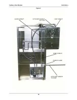
Connect neutral and ground as shown in Figure 6.
•
For three-phase operation, connect incoming power to terminals L1, L2 and L3 of the
contactor. Reconnect second receptacle inside hood electrical box to T2 and T3 on 1CR.
Connect neutral and ground as shown in Figure 6.
2. Insure that the fire extinguishing control box microswitch has been properly connected. Refer to
1g on page 8.
Содержание FH-28CT COUNTERTOP
Страница 1: ...CS TM 041 01 Revised 04 17 13 Ventless Hood System MODEL FH 28CT COUNTERTOP Service Manual ...
Страница 11: ...Ventless Hood System Installation 9 Figure 1 ...
Страница 12: ...Ventless Hood System Installation 10 Figure 2 ...
Страница 13: ...Ventless Hood System Installation 11 Figure 3 Right Side Pull Station Mounting ...
Страница 14: ...Ventless Hood System Installation 12 Figure 4 Left Side Pull Station Mounting ...
Страница 15: ...Ventless Hood System Installation 13 Figure 5 Complete Pull Station Mounting ...
Страница 24: ...Ventless Hood System Replacement Parts 22 Figure 7 Blower Motor Assembly ...
Страница 26: ...Ventless Hood System Replacement Parts 24 Figure 8 Right Side Cabinet Assembly ...
Страница 28: ...Ventless Hood System Wiring Diagrams 26 Wiring Diagrams ...
Страница 29: ...Ventless Hood System Notes 27 Notes ...

