Ventless Hood System
Installation
14
3. If required, connect the provided fire extinguishing system contacts for remote signaling. Refer to
the electrical diagram included in this manual (see page 26).
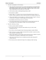
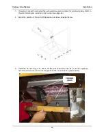
4. Adjust the position of the two ADP appliance nozzles as depicted below.
5. Install two UL Listed; type “A”, 165
°
F. fusible links (load rating 3-45 lbs.) in the two appliance
detector positions (one in front of the grease baffle, one behind the grease baffle).
FUSIBLE
LINKS
Содержание FH-28CT COUNTERTOP
Страница 1: ...CS TM 041 01 Revised 04 17 13 Ventless Hood System MODEL FH 28CT COUNTERTOP Service Manual ...
Страница 11: ...Ventless Hood System Installation 9 Figure 1 ...
Страница 12: ...Ventless Hood System Installation 10 Figure 2 ...
Страница 13: ...Ventless Hood System Installation 11 Figure 3 Right Side Pull Station Mounting ...
Страница 14: ...Ventless Hood System Installation 12 Figure 4 Left Side Pull Station Mounting ...
Страница 15: ...Ventless Hood System Installation 13 Figure 5 Complete Pull Station Mounting ...
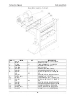
Страница 24: ...Ventless Hood System Replacement Parts 22 Figure 7 Blower Motor Assembly ...
Страница 26: ...Ventless Hood System Replacement Parts 24 Figure 8 Right Side Cabinet Assembly ...
Страница 28: ...Ventless Hood System Wiring Diagrams 26 Wiring Diagrams ...
Страница 29: ...Ventless Hood System Notes 27 Notes ...

