Automatic Lift Fryer
Operation
11
Item #
Description
Function
1
Computer
Used to program the cooking computer and activate the
programs.
2
Momentary Switch
BASKET UP – Momentarily pushing the switch to this position
causes the lift mechanism to rise. This is enabled only when the
FILTER/OFF/FRY switch is in the FRY position.
BASKET DOWN – Momentarily pushing the switch to this position
causes the lift mechanism to lower. This is enabled only when the
FILTER/OFF/FRY switch is in the FRY position.
3
Rocker Switch
FILTER – When placed in this position, power is applied to the
motor and shorting is pumped into the pot directly or thru the fill
hose.
OFF – When placed in this position, power is removed from the
pump motor, heating elements and lift mechanism.
FRY – When placed in this position, power is supplied to the
thermostat, heating elements and lift mechanism.
4
Thermostat Knob
Used to set the temperature of the shortening.
5
Thermostat Light
Illuminates to indicate that the set temperature of the shortening
has been reached.
6
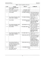
Digital Timer
The digital timer consists of an LED, display, beeper and 8
buttons described below:
LED indicator
Prior to the start of a timing cycle the LED will be OFF. When
running a timing cycle the LED will flash. At the end of a timing
cycle the LED will turn ON steady. When idle the LED is off.
TIME SELECT (2
arrow buttons)
Two arrow buttons on the front panel are used to set the time.
Hold the UP ARROW button down to increase the time. The
longer the button is held down, the faster the rate at which the
time will increase. The DOWN ARROW button is used in the
same manner as the UP ARROW button except it will cause the
time to decrease. The time is increased or decreased in 30-
second increments.
START/STOP
button
Starting the Timer
- Pressing this button while the timer is not
active will cause the timer to begin counting down the time on the
display.
Stopping the Timer -
Pressing this button while the timer is
active will stop the timer from counting down and display the
remaining time. Time cannot be changed with the TIME SELECT
buttons at this point. If this button is pressed again the timer will
continue counting down from the point it was stopped.
Resetting the Timer
- Pressing and holding this button for longer
than two (2) seconds will reset the timer and the display will return
to the original starting time. At this point, time can be changed
using the TIME SELECT buttons or the preset buttons.
Canceling The STIR OIL Function
- Pressing this button cancels
the STIR OIL function while it is active.
Содержание BLF-F
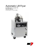
Страница 1: ...Automatic Lift Fryer MODELS BLF F BLF FC Service Manual Serial Numbers 137733 and higher ...
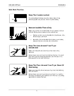
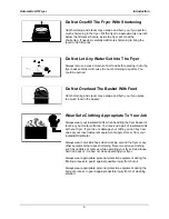
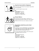
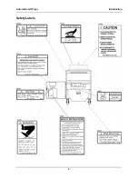
Страница 10: ...Automatic Lift Fryer Introduction 8 Safety Labels ...
Страница 28: ...Automatic Lift Fryer Replacement Parts 26 Figure 4 Drain Valve Plugs ...
Страница 30: ...Automatic Lift Fryer Replacement Parts 28 Figure 5 Drain Motor Piping Assembly ...
Страница 36: ...Automatic Lift Fryer Replacement Parts 34 Figure 10 Oil Vat Assembly ...
Страница 42: ...Automatic Lift Fryer Replacement Parts 40 7 8 9 10 11 12 13 14 15 16 17 ...
Страница 44: ...Automatic Lift Fryer Wiring Diagrams 42 Figure 16 BLF BLF F 208 220V 240V 3 Phase M ...
Страница 45: ...Automatic Lift Fryer Wiring Diagrams 43 Figure 17 BLF BLF F 220V 380V 230V 400V 240V 415V 3 Phase M ...
Страница 46: ...Automatic Lift Fryer Wiring Diagrams 44 Figure 18 Domestic BLF FC 208V 220V 240V Sheet 1 of 4 ...
Страница 47: ...Automatic Lift Fryer Wiring Diagrams 45 Figure 18 Domestic BLF FC 208V 220V 240V Sheet 2 of 4 ...
Страница 48: ...Automatic Lift Fryer Wiring Diagrams 46 Figure 18 Domestic BLF FC 208V 220V 240V Sheet 3 of 4 ...
Страница 49: ...Automatic Lift Fryer Wiring Diagrams 47 Figure 18 Domestic BLF FC 208V 220V 240V Sheet 4 of 4 ...
Страница 50: ...Automatic Lift Fryer Wiring Diagrams 48 Figure 19 European BLF FC 220V 380V 230V 400V 240V 415V Sheet 1 of 4 ...
Страница 51: ...Automatic Lift Fryer Wiring Diagrams 49 Figure 19 European BLF FC 220V 380V 230V 400V 240V 415V Sheet 2 of 4 ...
Страница 52: ...Automatic Lift Fryer Wiring Diagrams 50 Figure 19 European BLF FC 220V 380V 230V 400V 240V 415V Sheet 3 of 4 ...
Страница 53: ...Automatic Lift Fryer Wiring Diagrams 51 Figure 19 European BLF FC 220V 380V 230V 400V 240V 415V Sheet 4 of 4 ...
Страница 54: ...Automatic Lift Fryer Notes 52 Notes ...
Страница 55: ...Automatic Lift Fryer 53 ...
Страница 56: ...P O Box 80400 Simpsonville S C 29680 0400 USA http www bkideas com Made and printed in the U S A LI0226 0808 ...

