background image


Instrumen

t c

overs


must


not

 be r

emove

by

 o

perating


personnel.

 C

omponent

 r

eplacemen

t a

nd


internal

 a

djustments


mus

t b

e

 m

ade


by


qualifie

d s

ervice-traine

d m

aintenance

 pe

rsonnel

 w

ho


are

 a

ware

 of t

he


hazards


involve

d w

he

the

 i

nstrument's

 c

overs

 a

n

d s

hields

 a

re


removed

Under

 c

ertai

n c

onditions,

 e

ve

n w

it

h t

he

 p

ower

 c

or

removed,

 da

ngerous

 v

oltages


may

 e

xis

whe

the

 c

overs

 a

re


removed.


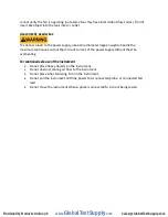
To

 a

void

 i

njuries,

 a

lways

 di

sconnec

the


power

 c

or

d fr

om

 t

he


instrument,


disconnec

t a

ll

 o

ther

 c

onnections

 (

for


example,

 t

es

t l

eads,

 c

ompute

r i

nterface


cables,

 e

tc.),

 d

ischarge

 all c

ircuits,

 an

d

 v

erify

 t

here

 ar

e

 n

o

 h

azardous

 v

oltages

 p

resent

 o

n

 an

y


conductors


by

 m

easurements

 w

i

th 

a

 pr

operly-operating

 v

oltage-sensing

 de

vice

 be

fore


touching


any

 in

terna

l p

arts.

 V

erify


the

 v

oltage-sensing


device

 is w

orking


properly

 b

efore

 a

nd

 a

fte

r mak

ing


the

 m

easurements


by

 te

sting

 wi

th

 kno

wn-operating

 v

oltage

 s

ources


and

 t

es

for

 bo

th


DC


and


AC


voltages.

 D

o

 n

ot

 a

ttempt

 an

y

 s

ervice


o

r a

djustment


unless

 an

othe

person

 c

apable

 o

f

 r

endering


firs

t a

i

d a

nd

 r

esuscitatio

n i

s

 pr

esent.


Do


not

 i

nser

t a

ny

 o

bject

 i

nto

 an 

instrument's

 v

entilation

 o

penings

 o

r

 o

ther


openings.


Hazardous

 v

oltages

 m

ay


be


present

 i

n

 une

xpecte

d l

ocations

 in c

ircuitry

 b

eing

 t

este

d w

he

n a 

faul

t c

onditio

n in 

the

 c

ircui

t e

xists.


Fuse replacement 


Fuse

 r

eplacemen

t m

us

be


done


by

 q

ualified

 s

ervice-trained

 main

tenance


personne

l w

ho

 ar

e


aware

 o

f

 t

he

 i

nstrument's

 fus

e

 r

equirements

 a

n

safe


replacemen

t pr

ocedures.


Disconnec

the


instrumen

from


the

 p

ower

 l

ine


before

 r

eplacing

 fus

es.

 R

eplace


fuses


only

 w

i

th n

ew


fuses


of

 t

he


fuse


types,

 v

oltage

 r

atings,

 a

nd

 c

urren

t r

atings

 s

pecifie

d in 

this

 m

anual

 o

r

 on t

he


back

 o

f

 t

he


instrument.

 F

ailure


to

 d

o

 s

o

 ma

y


damage


the

 in

strument,

 le

ad


to

 a s

afety

 h

azard,

 o

r

 c

ause

 a f

ire.


Failure


to

 us

e

 t

he

 s

pecifie

fuses


w

ill v

oid


the

 w

arranty.


Servicing 


Do


not

 s

ubstitute

 pa

rts


tha

t a

re

 not a

pproved

 by 

B&K

 P

recision

 o

r


modify


this

 i

nstrument.


Retur

the

 i

nstrumen

t t

o

 B

&K

 P

recisio

for

 s

ervice

 a

n

d r

epair

 t

o

 e

nsure


tha

t s

afety

 a

n

performance


features

 a

re

 main

tained.


Cooling fans 


This

 i

nstrumen

t c

ontains


one


or

 m

ore

 c

ooling

 f

ans.

 F

or

 c

ontinue

d s

afe


operation

 o

f

 t

he


instrument,


the

 a

ir

 i

nlet


a

nd e

xhaust

 o

penings

 f

or

 th

ese


fans

 m

ust

 n

o

be


blocke

nor

 m

us

accumulated

 d

ust


or


othe

debris

 b

e

 allo

wed


to


reduce

 air f

low.


Maintain

 a

t


least

 2

5


mm


clearance

 a

roun

the

 s

ides

 o

f

 t

he

 i

nstrumen

that

 c

ontai

n a

ir

 i

nle

t a

nd

 e

xhaus

ports.

 I

f


mounted

 in a r

ack,

 p

osition


powe

devices

 in t

he


rack

 ab

ove

 t

he

 i

nstrument


to


minimize


instrumen

heating

 w

hile

 r

ack

 m

ounted.

 D

o


not

 c

ontinue


to

 o

perate


the

 i

nstrume

nt if y

o

www.

GlobalTestSupply

.com

Find Quality Products Online at:

[email protected]

Содержание 9129B

Страница 1: ...Model 9129B Triple Output Programmable DC Power Supply USER MANUAL www GlobalTestSupply com Find Quality Products Online at sales GlobalTestSupply com...

Страница 2: ...associated with these category ratings The category rating is a Roman numeral of I II III or IV This rating is also accompanied by a maximum voltage of the circuit to be tested which defines the volta...

Страница 3: ...tlet The power jack and mating plug of the power cable meet IEC safety standards Do not alter or defeat the ground connection Without the safety ground connection all accessible conductive parts inclu...

Страница 4: ...ration and or mechanical shocks acoustic noise electrical noise strong electric fields or strong magnetic fields Do not operate instrument if damaged If the instrument is damaged appears to be damaged...

Страница 5: ...ondition in the circuit exists Fuse replacement Fuse replacement must be done by qualified service trained maintenance personnel who are aware of the instrument s fuse requirements and safe replacemen...

Страница 6: ...rrent of the power supply without the wire overheating For continued safe use of the instrument Do not place heavy objects on the instrument Do not obstruct cooling air flow to the instrument Do not p...

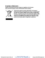
Страница 7: ...of the European Union on waste electrical and electronic equipment WEEE and in jurisdictions adopting that Directive is marked as being put on the market after August 13 2005 and should not be dispos...

Страница 8: ...2004 108 EC Electromagnetic Compatibility Directive with the following standards Low Voltage Directive EN61010 1 2001 EMC Directive EN 61000 3 2 2006 EN 61000 3 3 1995 A1 2001 A2 2005 EN 61000 4 2 3 4...

Страница 9: ...the instrument Direct current Alternating current Fuse Symbol Chassis earth ground symbol Ground terminal Protective earth ground CAUTION indicates a hazardous situation which if not avoided will res...

Страница 10: ...d Description 6 1 8 Display Overview 7 Display Description 7 2 Getting Started 8 2 1 Input Power and Fuse Requirements 8 Input Power 8 Fuse Requirements 9 2 2 Line Voltage Selection 9 2 3 Output Conne...

Страница 11: ...ock 24 4 Protections 25 Over Temperature Protection 25 Over Voltage Protection OVP 25 5 Remote Operation 26 Communication cables 26 USB to TTL Adapter IT E132B 26 RS 232 Settings 27 6 Remote Commands...

Страница 12: ...ating states and enable disable individual outputs Features 3 Independent fully programmable and electrically isolated outputs Series or parallel operation CH1 and CH2 Simultaneous voltage and current...

Страница 13: ...ipped with the following contents 1 x 9129B Power Supply 1 x AC Power Cord 1 x Certificate of Calibration 1 x Test Report 1 x TTL to USB serial adapter IT E132B Verify that all items above are include...

Страница 14: ...le grasp the handle by its sides pull outwards and rotate it until the arrow on the handle and the arrow on the plastic ears are in opposite directions Then pull the handle outward After removing the...

Страница 15: ...el View Front Panel Description VFD display Shift key Local key Power key Numeric keys Function keys Cursor keys Output terminals Rotary knob 1 2 3 4 5 6 7 8 9 www GlobalTestSupply com Find Quality Pr...

Страница 16: ...ure 2 Rear Panel View Rear Panel Description Cooling fan AC power input receptacle fuse box 110 220 V Power Switch RS 232 TTL interface 1 2 3 4 www GlobalTestSupply com Find Quality Products Online at...

Страница 17: ...gures output current or allows access to the power supply menu settings Recall Save button Saves and recalls instrument settings Meter button Switches from set value display to metered output value di...

Страница 18: ...in constant voltage mode CC The power supply is in constant current mode Indicates shift mode for access to secondary button functions Indicates remote mode Indicates the channel currently selected SE...

Страница 19: ...patible with the rated voltage current and that there is sufficient circuit capacity for the power supply Once verified connect the cable firmly The included AC power cord is safety certified for this...

Страница 20: ...ired AC line voltage please follow the steps below For safety no power should be applied to the instrument while changing line voltage operation Disconnect all cables connected to the instrument befor...

Страница 21: ...Line Voltage Switch Location Do not connect power to the instrument until the line voltage selection is setup correctly Applying an incorrect line voltage or configuring the line voltage selection im...

Страница 22: ...cidental contact with hazardous voltages ensure that the load and its connections have no accessible live parts Ensure that the load wiring insulation rating is greater than to the maximum output volt...

Страница 23: ...any of these messages for about 2 seconds on initialization Output Check Voltage Check Follow the steps below to check basic voltage output with no load connected 1 Turn on the power supply The VFD w...

Страница 24: ...heck current output of the power supply 1 Turn off all output channels button will not be illuminated 2 Short the and output terminals with test leads or a shorting bar 3 Adjust the voltage value of C...

Страница 25: ...put terminals Check Model and Firmware Version The model and firmware version can be verified by sending the IDN remote command It can also be found from within the menu system by following these step...

Страница 26: ...s menu structure and learn how to view or change settings and parameters Follow the steps below to guide you in selecting menu options 1 From the normal display press the key and then the button to en...

Страница 27: ...e user to turn the beep sound for key press confirmation on or off 1 From the MENU navigate to bEEP using the keys There are two options that can be selected by using the keys or rotary knob 2 Select...

Страница 28: ...rp2 Grp3 Each group has 9 locations therefore allowing the customer to save 27 output state configurations 2 Select one of the three memory location groups and then press the button The cursor will mo...

Страница 29: ...uble the available voltage range that can be supplied by combining the voltage of channels 1 2 The maximum output voltage of SEr mode becomes 60 V Follow the steps below to enable this feature 1 Power...

Страница 30: ...ot illuminated press the button once to display the measured voltage and current at the output Parallel Mode PAr Parallel mode will increase the available current range that can be supplied to 6 A max...

Страница 31: ...g mode is only available for CH1 and CH2 The voltage or current in these two channels will operate synchronously The tracking is based on a ratio between CH1 and CH2 For example if the voltage is the...

Страница 32: ...prevent accidental changes to the output settings that exceeds the DUT device under test limit Follow the steps below to set the LVP limit 1 Press the key to select channel 2 Press the key and then p...

Страница 33: ...ated by press for voltage or for current then press to move the cursor position and adjust the voltage or current value using the rotory knob 3 Using the Up Down arrows Press key to select channel sel...

Страница 34: ...the and then the button to enter Save mode The button will blink until a Save location value is entered 1 9 2 Use the numeric keypad to enter the memory location locations 1 to 9 to store the setting...

Страница 35: ...and then the button The button will illuminate indicating that the front panel keys are locked At this point all keys are disabled except for and the buttons 2 To unlock the keys press the key and the...

Страница 36: ...Warning Over Voltage Protection OVP The 9129B has over voltage protection function which may be triggered due to an internal error wrong operation by the customer or over voltage at the output termin...

Страница 37: ...MENT side of the adapter to the DC load DB9 connector Connect the COMPUTER end to a USB port on your computer When connected the computer will automatically install the appropriate drivers For Windows...

Страница 38: ...how to select a different baud rate Note The remote interface does not have a flow control mechanism The programmer should be aware of this limitation and allow sufficient command process time If the...

Страница 39: ...some instrument specific commands These commands enable a computer to remotely communicate and control the instrument over serial using the TTL to USB serial adapter IT E132B www GlobalTestSupply com...

Страница 40: ...C mode Q Why is my display voltage lower than the voltage I set This is often because of the resistances from the test leads wires connected between the supply and the DUT device under test which caus...

Страница 41: ...ing Voltage 0 30 V CH1 CH2 0 5 V CH3 Current 0 3 A All Channels Power Line Regulation Voltage 0 02 4 mV Current 0 2 3 mA Load Regulation Voltage 0 02 4 mV Current 0 20 3 mA Ripple and Noise Voltage 5...

Страница 42: ...ual com via IT E132B adapter AC Input 110 220 VAC 10 47 Hz 63 Hz Operating Temperature 32 F to 104 F 0 C to 40 C Storage Temperature 4 F to 158 F 20 C to 70 C Dimensions W H D 8 45 x 3 47 x 13 96 214...

Страница 43: ...Calibration We recommend a calibration interval of once per year to ensure that the power supply meets specifications www GlobalTestSupply com Find Quality Products Online at sales GlobalTestSupply co...

Страница 44: ...ctors and accessories that you are using with the device Customers not on an open account must include payment in the form of a money order or credit card For the most current repair charges please re...

Страница 45: ...This warranty does not apply in the event of misuse or abuse of the product or as a result of unauthorized alterations or repairs The warranty is void if the serial number is altered defaced or remove...

Страница 46: ...2015 B K Precision Corp v090915 www GlobalTestSupply com Find Quality Products Online at sales GlobalTestSupply com...

Отзывы: