3.
Using
t
he
numeric
k
eypa
d o
r
t
he
v
oltage
a
djus
t
rotary
knob,
ente
r a v
oltage
v
alue.
Th
e
voltage
display
w
ill
now
show
th
e
v
alue
y
o
u e
ntered.
If e
ntering
w
it
h
numeric
k
eypad,
press
the
button
first,
t
hen
ente
r t
he
value
and
p
ress
the
button.
4.
I
f t
he
butto
n i
s
not a
lready
illuminated,
pr
ess
it
once
to
display
the
measured
voltage
at
the
o
utput
.
The
v
oltage
may
fl
uctuate
slightly
fr
om
the
value
e
ntere
d i
n
t
he
previous
s
tep.
5.
(Optional)
You
m
ay
a
lso
verify
t
he
outp
ut v
oltage
by c
onnecting
the
(
+)
a
nd
(-)
t
erminals
t
o
a
n e
xternal
v
oltmeter.
T
he
m
easure
d v
alue
s
houl
d m
atc
h o
r
b
e
comparable
t
o
th
e en
tered
voltage
v
alue.
6.
Check
the o
ther
tw
o
c
hannels
following
t
he
s
ame
pr
ocedure.
Current Check
Follo
w
the
s
teps
be
lo
w
to
c
hec
k
curren
t o
utpu
t of t
he
powe
r s
upply.
1.
Turn
o
f
f a
ll
o
utpu
t c
hannels
(
butto
n
w
ill
not
b
e
illuminated).
2.
Shor
t th
e
(
+)
a
n
d (
-)
o
utp
ut
terminals
w
it
h
test
l
eads
o
r a
shorting
ba
r.
3.
Adjus
t t
he
v
oltage
v
alue
o
f C
hannel
1 to 3
V.
4.
Press
the
butto
n
to
e
nable
the
o
utput.
The
C
V
i
ndicator
will c
hange
imme
diately
to
C
C
i
ndicating
the
po
wer
s
upply
is
in
constant
c
urrent
mode.
The C
C
mode
all
ows
the
supply
t
o
adjust
the
c
urrent
o
utput.
The
v
oltage
automatically
a
djusts
to
m
aintai
n the
relationship
o
f
c
urrent,
v
oltage
and
re
sistance
according
t
o
O
hm’s
L
aw.
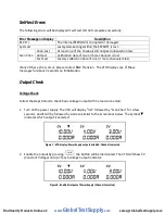
Figure 10 - VFD display: Outputs of Power Supply disabled. Channel 1 selected.
5.
Set
different
c
urrent
v
alues
betwee
n 0
A
a
n
d 3
A
.
Pre
ss
the
butto
n
and
observ
e
ho
w th
e
voltage
v
alue
on
the
V
F
D
is
ap
proximately
0
volts.
Figure 9 – VFD display: Outputs of Power Supply disabled. Channel 1 selected.
www.
GlobalTestSupply
.com
Find Quality Products Online at:


