CB-100-1
66
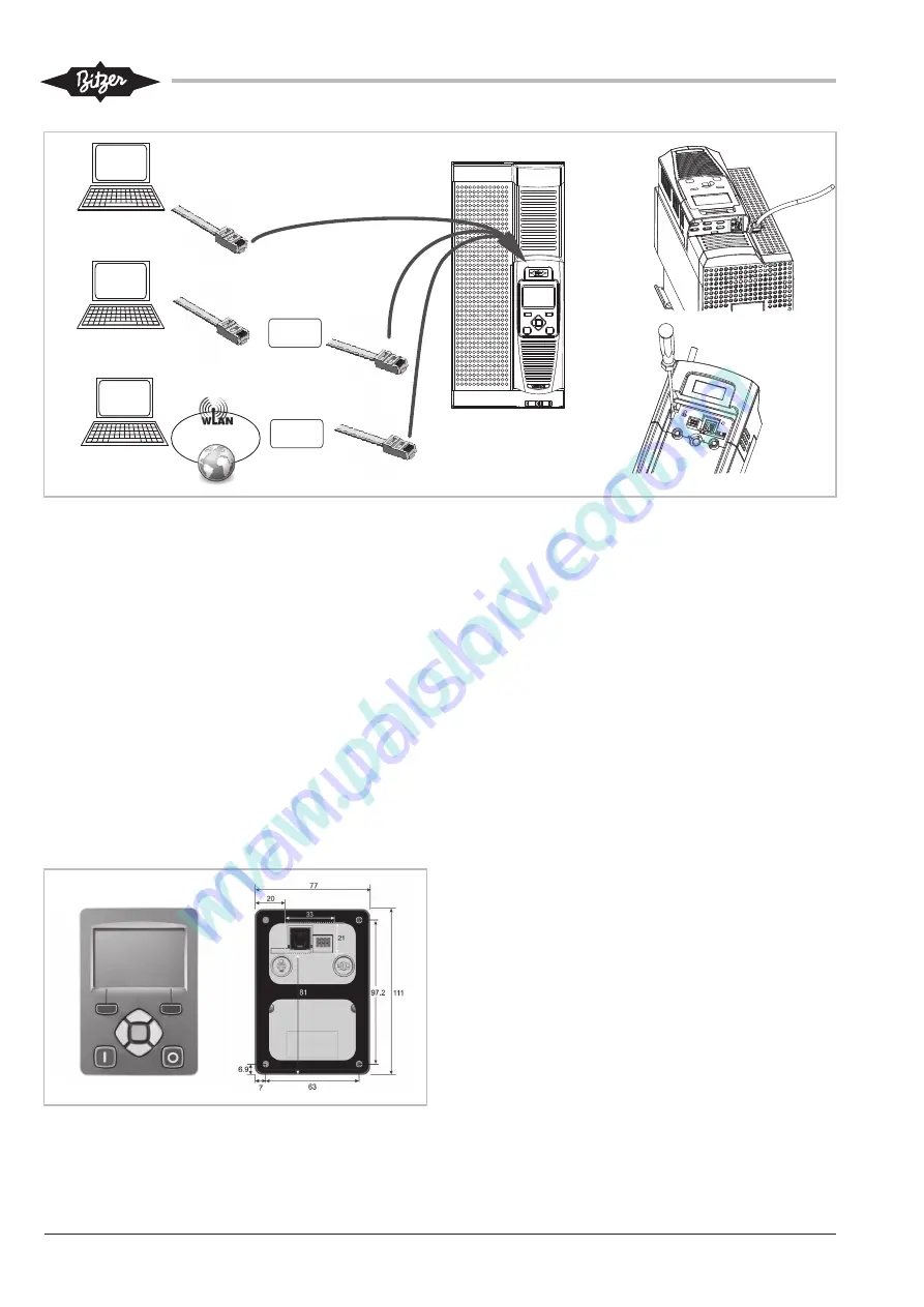
Router
BEST
Software
RJ45
RJ45
BEST
Software
BEST
Software
RJ45
Router
RJ45
1)
2)
3)
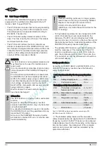
Fig. 19: Plug the network cable into the RJ45 slot at the VARIPACK and unplug it again
Establishing communication with the BEST software:
see chapter Commissioning of the VARIPACK fre-
quency inverter, page 67.
7.2
Removable control panel (with display and
keypad)
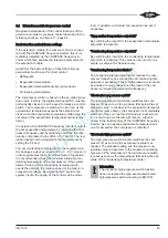
The VARIPACK frequency inverter can be configured
and monitored completely via the optional removable
control panel (with display and keypad). To do so, in-
sert the SD card delivered with the control panel into
the SD card slot. Afterwards plug the control panel
either directly in the front panel (instead of the cover)
(see figure 7, page 46) or mount it on the outside of the
switch cabinet or on the switch cabinet door using the
kit for external mounting.
Fig. 20: Front and rear view of the control panel with fixing holes and
recess on the back (for external mounting to the switch cabinet)
7.2.1
Kit for external mounting of the control panel
The kit for external mounting of the optional control
panel (part number 347 97 10) consists of:
• Connecting cable (3 m long)
• 4 mounting screws.
Mounting (see figure 20, page 66):
• Mount the control panel on a flat surface, for ex-
ample on the outside of the switch cabinet door.
• Take the recess on the switch cabinet door for the
connections on the back of the control panel into ac-
count (see figure 20, page 66)!
7.2.2
Control panel setup and operation
For this, please refer to the BITZER leaflet 378 204 05
delivered with the control panel.
7.3
Interfaces for communication via Modbus RTU
and Modbus TCP/IP
For communication with higher-ranking system control-
lers or the building control system, the following inter-
faces are additionally available:
• Modbus RTU via RS485
• Modbus TCP/IP via RJ45 network cable
For the explanation and set-up of these interfaces, in-
cluding the register or address definition, see Refer-
ence Guide CG-100.
Содержание VARIPACK FDU+12
Страница 12: ...CB 100 1 12 1 2 3 4 Abb 7 Steuremodul abmontieren...
Страница 46: ...CB 100 1 46 1 2 3 4 Fig 7 Dismounting the control module...
Страница 64: ...CB 100 1 64 Fig 17 Graphical representation of the general control functions of the extension module...
Страница 70: ...Notes...
Страница 71: ...Notes...

