1
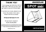
P A R T S L I S T
Item
Qty
Description
Item
Qty
Description
A
4
Wheel
H
4
1/2” X 1 Carriage Bolt
B
4
Wheel Lever
I
4
5/8” Lock Nut
C
4
Lever Bracket
O
4
1/2” Lock Nut
D
4
Safety Channel
P
12
1.66” Round Clamp Assembly
E
4
Hand Knob
Q
12
2” Round Clamp Assembly
F
4
Wing Nut
R
12
2” Square Clamp Assembly
G
4
5/8” X 3” Carriage Bolt
♦
Inspect all contents prior to installation. Report any missing parts to dealer immediately.
♦
Read all instructions before proceeding.
SC04WKU
Universal Portable Soccer Goal Wheel Kit
Date: 11/02/06 Rev: I.R. B.A. N.J.C. File: \drive.f\pub\sc04wkinst Ref#: 860127
Customer Service
(800) 247-7668
—— Instruction Manual ——
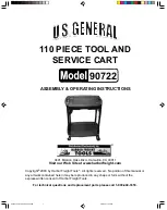
1. Determine the size of your back stay material, these wheel kits will work on 1.66” and 2” round or 2”
square. Select to appropriate
Clamp Assemblies (P, Q or R)
.
2. Install
Lever Bracket (C)
and
Safety Channel (D)
onto the back stay with The Clamp Assembly selected
from instruction #1. This wheel assembly works the best when you install as close to the vertical
uprights as possible. Make sure the vertical leg of the
Lever Bracket (C)
is positioned to the outside of
the goal and level. See illustration on page #2.
3. Attach
Wheel (A)
to
Wheel Lever (B)
in the larger of the two square holes with the
5/8” X 3” Carriage
Bolt (G)
and
5/8” Lock Nut (I)
. One side of the
Wheel (A)
has a hub that allows clearance for the
Wheel
Lever (B)
and you want the
Lock Nut (I)
on the outside of the wheel. Keep in mind that you will need a
right and left assembly, it is best to lay all of the parts out next to each upright, orient prior to assembly.
Once you have both wheels assembled onto the wheel levers you can now attach the wheel lever to the
Lever Bracket (C)
with the
1/2” X 1” Carriage Bolt (H)
and the
1/2 Lock Nut (O).
Make sure the
Carriage Bolt is firmly seated in the square hole on the Lever. Tighten 1/2” hardware and back off 1/2
turn until the
Wheel Lever (B)
can rotate freely. See illustration on page #2
4. Use
the
Hand Knob (E)
and
Wing Nut (F)
to lock
Wheel (A)
in position for transport. Once goal is
positioned for play remove
Hand Knob (E)
and
Wing Nut (F).
Rotate Wheel up and back until resting
on the playing surface away from the front of the goal. Replace
Hand Knob (E)
and
Wing Nut (F)
into
the
Wheel
Lever (B)
for storage. See illustration on page #2.