Setting options for parameters and values
2
Example of a sensitivity setting
Notes on setting options:
Adjusting the angle
Initialisation
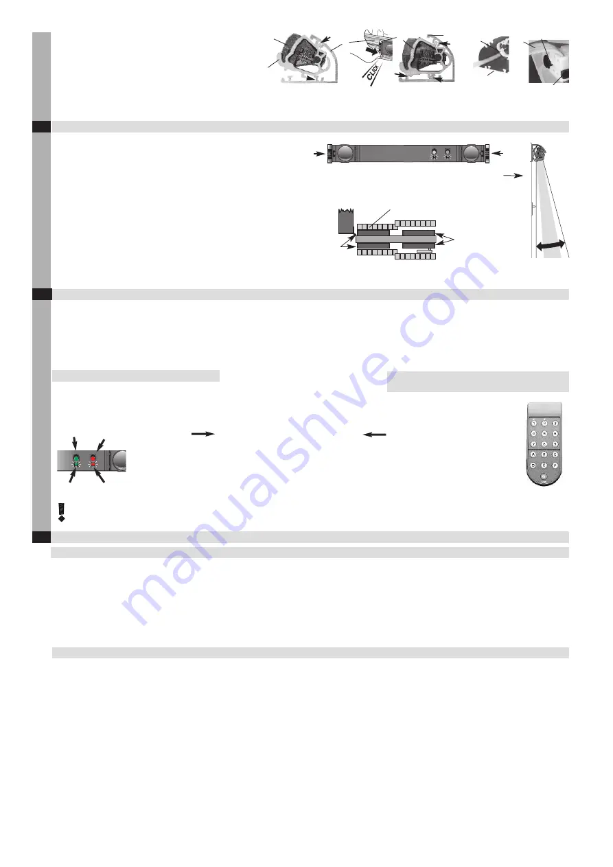
1. Click sensors
and
b onto the aluminium profile
. Insert the
upper lug of the mounting clips
into the upper groove of the profile
,
then click into place.
2. There is space for the cables between the mounting clip
and the profile
.
3. Use the ribbon cable
to connect the individual sensors
and
b (note the narrow and wide grooves, do not use force
to insert the cable).
Setting the inclination angle
2.4
Initialisation of a sensor
2.5
3
To ensure correct functioning,
the same angle must be set on the left and
right sides of a sensor.
The position of the detection field
10 is determined by the position of the
US beam in the aluminium profile.
Push the sensor as far as possible to the left or right end of the profile in
order to protect the closing edges.
The inclination angle of each sensor must be selected such that the door stops
BEFORE
it comes into contact with an obstacle.
The inclination angle values specified cover 90% of all applications. For special
applications, refer to your application documents.
2–14°
Adjustable
inclination anglel
2° – 14° (3° angle)
5°
5°
5°
8°
2°
2°
14°
2°
14°
A sensor must always be initialised on the master module on each start-up (first initialisation).
Notes on initialisation for special backgrounds:
In the case of special backgrounds (such as a metal grating), place a cardboard on the background in order to ensure faultless initialisation (see the table in chapter 5
relating to background composition parameters).
Nature of the background:
• One of 3 setting options must be selected, depending on the composition of
the ground being used. If the red LED blinks twice and there is no object in the
sensorfield, a special background has to be set:
– Standard
– Very dark and/or reflecting ground
– Metal grating -> A base must be placed over the grating during initialisation
(the sensitivity is then fixed at >= 50 cm). This setting will switch off the
background test and –tracking function.
Synchronisation:
• Synchronisation is active in standard mode and ensures that the sensors will
continue to work faultlessly even if fields overlap.
– Caution: If a US beam (green label) or a R3 (yellow label) is used
together with an older release, synchronisation must be switched off and
overlapping prevented manually (various levels, switch off beams).
Master-initialisation using the «green» key:
«green» key
«green» LED
«red» key
«red» LED
Master-initialisation using the remote control
(RegloBeam 2):
After initialisation, the sensor is ready for operation. Please check the sensor’s detection responses. If they do not meet your
requirements, you can use the sensor’s keys or the remote control to set various detailed configurations and optimise your door
system's functionality (see next chapter).
1. Both the red and green LEDs flash to show that the
initialisation procedure has been triggered. You now
have 6 seconds to leave the detection field.
2. The red LED flashes to show that initialisation is
being performed. Do
not
enter the detection field.
3. If the LEDs continue to flash as before, please refer
to chapter 4, Troubleshooting.
4. Once both LEDs cease to flash, initialisation
is complete.
Press the
«green»
key for
5 seconds
to trigger the
master-initialisation procedure. Trigger the master-
initialisation only on the sensor which is connected
with the door controller.
Initialisation:
1. Press key
«G»
2. Press keys
F + 3 + 6
to trigger the
initialisation procedure
3. lock the remote control:
F + 3 + 8
The remote control is available as an
optional accessory.
1.Press the «red» and «green» keys for 1 second, -> device located
at parameter 1, «test input».
2.Press the «red» key 3 times -> device moves to parameter 4, «sensitivity»
and indicates a value of 3 (20 cm) by flashing green 3 times
3.Press the «green» key twice -> device indicates a value of 5 (40 cm) by
flashing green 5 times.
4.Optional: Exit setting mode by pressing the “red” and “green” keys
for 1 second.
1. Press key «G» on the remote control («3» lights up for the device with address 3, for
example).
2. Press key «D»; key «3» lights up, i.e. the previous value was 3 (20 cm).
3. Press key «5»; a value of 5 (40 cm) is set (key «5» lights up).
Note:
The parameterisation by remote control will be locked after 30 min without operation.
Reactivation: briefly press the green key, switch the supply on/off or enter an actication
code.
Setting using the «red» and «green» keys:
Setting using the remote control:
Sensitivity:
• The sensitivity value must be selected on-site in accordance with requirements
(e.g. EN 16005).
– The values specified are guide values and relate to the height of the object to be detected.
This will vary depending on the composition of the background and must be checked on-site.
Initialisation:
• The mounting height of the sensors is memorised during initialisation.
– The corresponding specified height is saved in parameter 8 using values 1 – 4 (1 = 1.4 – 1.7 m
approx., 2 = 1.7 – 2 m approx., 3 = 2.0 – 2.4 m approx., 4 = 2.4 – 3.0 m approx.).
Restoring the factory default setting:
•
Press both the “red” and “green” keys for 5 seconds until the red LED flashes
rapidly, then release them.
Enhanced levels
Standard mode sets all values to their factory default settings and switches all light beams on.
Power saving mode sets all values to their factory default settings and switches light beams 2, 4
and 6 off.
Narrow groove
IV
V
2°
14°
1.
2.
3.
Wide groove
Upper groove
Sensor clicked into place
door leaf


