background image

Hi-Fi A85W/Hi-Fi A75W 

41 

CHAPTER 7: USEFUL HELP 

7.1 D

RIVER 

I

NSTALLATION 

N

OTE


After you installed your operating system, please insert the Fully Setup 
Driver DVD into your optical drive and install the driver for better system 
performance. 
 
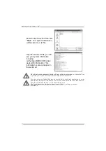
You will see the following window after you insert the DVD 


The setup guide will auto detect your motherboard and operating system. 

 
Note:


If this window didn’t show up after you insert the Driver DVD, please use file browser to 
locate and execute the file SETUP.EXE under your optical drive. 

A. Driver Installation 

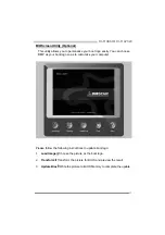
To install the driver, please click on the Driver icon. The setup guide will 
list the compatible driver for your motherboard and operating system. 
Click on each device driver to launch the installation program. 

B. Software Installation 

To install the software, please click on the Software icon. The setup guide 
will list the software available for your system, click on each software title 
to launch the installation program. 

C. Manual 

Aside from the paperback manual, we also provide manual in the Driver 
DVD. Click on the Manual icon to browse for available manual. 

 
Note:


You will need Acrobat Reader to open the manual file. Please download the latest version of 
Acrobat Reader software from 

http://get.adobe.com/reader/


Содержание Hi-Fi A75W

Страница 1: ...e right to revise this publication and to make changes to the contents here without obligation to notify any party beforehand Duplication of this publication in part or in whole is not allowed without first obtaining the vendor s approval in writing The content of this user s manual is subject to be changed without notice and we will not be responsible for any mistakes found in this user s manual ...

Страница 2: ... 4 AMD DUAL Graphics Technology 18 4 1 AMD Dual Graphics Technology Introduction 18 4 2 AMD Dual Graphics Requirement 18 4 3 AMD Dual Graphics Setup 19 Chapter 5 RAID Functions 20 5 1 Operating System 20 5 2 Raid Arrays 20 5 3 How RAID Works 20 Chapter 6 UEFI BIOS Software 24 6 1 UEFI BIOS 24 6 2 Software 27 6 3 BIOS Update 36 Chapter 7 Useful Help 41 7 1 Driver Installation Note 41 7 2 Extra Info...

Страница 3: ...motherboard or the rear side of the board unless necessary Hold the board on the edge do not try to bend or flex the board Do not leave any unfastened small parts inside the case after installation Loose parts will cause short circuits which may damage the equipment Keep the computer from dangerous area such as heat source humid air and water The operating temperatures of the computer should be 0 ...

Страница 4: ...a internal headers 8x USB 2 0 port 4 on rear I Os and 4 via internal headers Expansion Slots 2x PCI Slot 2x PCIe 2 0 x1 Slot 2x PCIe 2 0 x16 Slot x16 x4 Rear I Os 1x PS 2 Keyboard Mouse 1x HDMI Port 1x VGA Port 1x DVI Port 1x LAN port 4x USB 2 0 Port 2x USB 3 0 Port 6x Audio Jack Internal I Os Hi Fi A85W 8x SATA 6 0Gb s Connector 2x USB 2 0 Header each header supports 2 USB 2 0 ports 1x USB 3 0 He...

Страница 5: ...ndent display outputs Note 3 Since the audio chip supports High Definition Audio Specification the function of each audio jack can be defined by software The input output function of each audio jack listed above represents the default setting However when connecting external microphone to the audio port please use the Line In Blue and Mic In Pink audio jack Note 4 Maximum resolution Outputs Maximu...

Страница 6: ...Motherboard Manual 4 1 5 MOTHERBOARD LAYOUT Note represents the 1 st pin ...

Страница 7: ...ROCESSING UNIT CPU Step 1 Pull the socket locking out from the socket and then raise the lever up to a 90 degree angel Step 2 Look for the white triangle on socket and the gold triangle on CPU should point towards this white triangle The CPU will fit only in the correct orientation ...

Страница 8: ...anual 6 Step 3 Hold the CPU down firmly and then close the lever to locked the position Step 4 Put the CPU Fan on the CPU and buckle it Connect the CPU FAN power cable to the CPU_FAN1 This completes the installation ...

Страница 9: ...k wire to pin 1 CPU_FAN1 CPU Fan Header Pin Assignment 1 Ground 2 12V 3 FAN RPM rate sense 4 Smart Fan Control By Fan SYS_FAN1 2 System Fan Header Pin Assignment 1 Ground 2 12V 3 FAN RPM rate sense Note CPU_FAN1 SYS_FAN1 2 support 4 pin and 3 pin head connectors When connecting with wires onto connectors please note that the red wire is the positive and should be connected to pin 2 and the black w...

Страница 10: ...rboard Manual 8 2 3 INSTALLING SYSTEM MEMORY A DDR3 Modules 1 Unlock a DIMM slot by pressing the retaining clips outward Align a DIMM on the slot such that the notch on the DIMM matches the break on the slot ...

Страница 11: ...Memory Installation Please refer to the following requirements to activate Dual Channel function Install memory module of the same density in pairs shown in the table Dual Channel Status DDR3_A1 DDR3_A2 DDR3_B1 DDR3_B2 Enabled O X O X Enabled X O X O Enabled O O O O O means memory installed X means memory not installed Note The DRAM bus width of the memory module must be the same x8 or x16 D DDR S...

Страница 12: ...dby Voltage 5V 22 5V 10 12V 23 5V 11 12V 24 Ground 12 3 3V ATXPWR2 ATX Power Source Connector This connector will provide 12V to CPU power circuit Pin Assignment 1 12V 2 12V 3 Ground 4 Ground Note1 Before you power on the system please make sure that both ATXPWR1 and ATXPWR2 connectors have been plugged in Note2 Insufficient power supplied to the system may result in instability or the peripherals...

Страница 13: ...quipped with 2 standard PCI slots PCI stands for Peripheral Component Interconnect and it is a bus standard for expansion cards PEX16_1 PCI Express Gen2 x16 Slot PCI Express 2 0 compliant Maximum theoretical realized bandwidth of 8GB s simultaneously per direction for an aggregate of 16GB s totally PEX16_2 PCI Express Gen2 x4 Slot PCI Express 2 0 compliant Data transfer bandwidth up to 2GB s per d...

Страница 14: ... Serial ATA Connectors These connectors connect to SATA hard disk drives via SATA cables Hi Fi A85W supports 8 SATA 3 0 connectors Hi Fi A75W supports 6 SATA 3 0 connectors Pin Assignment 1 Ground 2 TX 3 TX 4 Ground 5 RX 6 RX 7 Ground ...

Страница 15: ...TTINGS PANEL1 Front Panel Header This 16 pin connector includes Power on Reset HDD LED Power LED and speaker connection It allows user to connect the PC case s front panel switch functions Pin Assignment Function Pin Assignment Function 1 5V 9 N A 2 N A 10 N A N A 3 N A 11 N A N A 4 Speaker Speaker Connector 12 Power LED 5 HDD LED 13 Power LED 6 HDD LED Hard drive LED 14 Power LED Power LED 7 Grou...

Страница 16: ...t 1 VBUS0 11 D2 2 SSRX1 12 D2 3 SSRX1 13 Ground 4 Ground 14 SSTX2 5 SSTX1 15 SSTX2 6 SSTX1 16 Ground 7 Ground 17 SSRX2 8 D1 18 SSRX2 9 D1 19 VBUS1 10 ID 20 Key F_USB1 F_USB2 Headers for USB 2 0 Ports at Front Panel This header allows user to connect additional USB cable on the PC front panel and also can be connected with a wide range of simultaneously accessible external Plug and Play peripherals...

Страница 17: ...ense 6 RT Line Out 7 Front Sense 7 Reserved 8 Key 8 Key 9 Left line in 9 LFT Line Out 10 Jack Sense 10 LFT Line Out Note1 It is recommended that you connect a high definition front panel audio module to this connector to avail of the motherboard s high definition audio capability Note2 Please try to disable the Front Panel Jack Detection if you want to use an AC 97 front audio output cable The fun...

Страница 18: ...OS data Clear CMOS Procedures 1 Remove AC power line 2 Set the jumper to Pin 2 3 close 3 Wait for five seconds 4 Set the jumper to Pin 1 2 close 5 Power on the AC 6 Load Optimal Defaults and save settings in CMOS J_COM1 Serial Port Connector The motherboard has a Serial Port Connector for connecting RS 232 Port Pin Assignment 1 Carrier detect 2 Received data 3 Transmitted data 4 Data terminal 5 Si...

Страница 19: ... IrDA serial output 6 IR Power On Board Buttons There are 2 on board buttons SW_PWR1 This is an on board Power Switch button SW_RST1 This is an on board Reset button BIOS POST Code CPU Temperature Indicator This indicator will show POST code while booting After the booting sequence it will show current CPU temperature Please refer to Chapter 7 4 for all the BIOS POST codes ...

Страница 20: ...g System Windows Vista Windows 7 Windows 8 Supported Dual Graphics Combinations AMD Radeon Graphics Card A10 Series HD 7660D A8 Series HD7560D A6 Series HD 7540D HD 6670 HD 6570 HD 6450 Recommended graphics cards for AMD dual graphics Note 1 A4 Series products do not support Dual Graphics Note 2 The information described above in this manual is for your reference only and the actual information an...

Страница 21: ...Graphics Ready graphics card into PEX16_1 slot Step 2 Set the BIOS setting as follows Chipset North Bridge Surround View Enabled Step 3 Install Driver DVD Chipset Driver and reboot the system Activate AMD VISION Engine Control Center to make sure CrossFire has been enabled ...

Страница 22: ...d performs disk reads and writes across multiple drives in parallel The size of each block is determined by the stripe size parameter which you set during the creation of the RAID set based on the system environment This technique reduces overall disk access time and offers high bandwidth Features and Benefits Drives Minimum 2 and maximum is up to 6 or 8 Depending on the platform Uses Intended for...

Страница 23: ... applied for high availability solutions or as a form of automatic backup that eliminates tedious manual backups to more expensive and less reliable media Features and Benefits Drives Minimum 2 and maximum is 2 Uses RAID 1 is ideal for small databases or any other application that requires fault tolerance and minimal capacity Benefits Provides 100 data redundancy Should one drive fail the controll...

Страница 24: ...is 6 or 8 depending on the platform Benefits Optimizes for both fault tolerance and performance allowing for automatic redundancy May be simultaneously used with other RAID levels in an array and allows for spare disks Drawbacks Requires twice the available disk space for data redundancy the same as RAID level 1 Fault Tolerance Yes Block 1 Block 3 Block 5 Block 2 Block 4 Block 6 Block 1 Block 3 Bl...

Страница 25: ...AID 5 function is supported by A85 chipset only Features and Benefits Drives Minimum 3 Uses RAID 5 is recommended for transaction processing and general purpose service Benefits An ideal combination of good performance good fault tolerance and high capacity and storage efficiency Drawbacks Individual block data transfer rate same as a single disk Write performance can be CPU intensive Fault Tolera...

Страница 26: ...em Manual Memory System Manual MCT System and Manual G P U System Note Not all types of CPU perform above overclock setting ideally the difference will be based on the selected CPU model WARNING For better system performance the UEFI BIOS firmware is being continuously updated The UEFI BIOS information described below in this manual is for your reference only and the actual UEFI BIOS information a...

Страница 27: ... system starts up However it can prevent system hang up due to inappropriate overclock actions When the system hangs up S R S will automatically log in the default UEFI BIOS setting and all overclock settings will be re configured C Smart Fan Function Smart Fan Function is under Smart Fan Control in Advanced Menu This is a brilliant feature to control CPU System Temperature vs Fan speed When enabl...

Страница 28: ...han this value the CPU fan will keep lowest RPM The range is from 0 50 with an interval of 1 Fan Ctrl On When CPU temperature is higher than this value the CPU fan controller will turn on The range is from 0 70 with an interval of 1 Fan Ctrl Start Value This item sets CPU FAN Start Speed Value The range is from 0 255 with an interval of 1 Fan Ctrl Sensitive The bigger the numeral is the higher the...

Страница 29: ...mpleted you will see the software icon showing on the desktop Double click the icon to launch it TOverclocker TOverclocker presents a simple Windows based system performance enhancement and manageability utility It features several powerful and easy to use tools such as Overclocking for enhancing system performance also for special enhancement on CPU and Memory Smart Fan management and PC health a...

Страница 30: ...ry tab provides information on the memory module s You can select memory module on a specific slot to see its information The OC Tweaker tab allows you to change system clock settings and voltages settings It also provides six pre set modes for you The screenshot below is for reference only ...

Страница 31: ... for different overclocking experience The screenshot below is for reference only The HW Monitor tab allows you to monitor hardware voltage fan speed and temperature Besides you also can set related values for CPU Smart Fan The screenshot below is for reference only ...

Страница 32: ...abling extra phases while CPU is on light loading it features 4 1 power phases current power saving and toal power saving This tool integrates a friendly GUI to monitor your CPU Usage CPU Watt and CPU Temperature Moreover it optimizes power saving and best power efficiency on your system The illustration below is for reference only Display manufacturer software version information Display CPU info...

Страница 33: ...p excellent performance Auto Phase Mode System switches the mode automatically according to current system loading condition Performance Mode This is the mode saving power consumption most Least energy will be used in the system Typical Mode Compared with that in Performance Mode energy consumption in this mode is a little bit more Medium Mode This is the standard system power saving mode Maxi Ene...

Страница 34: ...te Button To disable system sound z Volume Control Knob The volume can be finely adjusted by turning the knob either clockwise or anti clockwise to increase or decrease system volume accordingly z Information Button Get information of the application z Minimize Button Minimize the application window to the taskbar z Exit Button Exit the application Note 1 Smart EAR is only supported by Windows 7 a...

Страница 35: ...ess that you would like to send the copy to Provide the name of the power supply manufacturer and the model no Send the mail out Save these information to a txt file Exit this dialog Select your area or the area close to you Provide the name of the memory module manufacturer Describe condition of your system represents important information that you must provide Without this information you may no...

Страница 36: ...he sent mail We will not share customer s data with any other third parties so please feel free to provide your system information while using eHot Line service If you are not using Outlook Express as your default e mail client application you may need to save the system information to a txt file and send the file to our tech support with other e mail application Go to the following web http www b...

Страница 37: ...You can choose BMP as your boot logo so as to customize your computer Please follow the following instructions to update boot logo 1 Load Image Choose the picture as the boot logo 2 Transform Transform the picture for BIOS and preview the result 3 Update Bios Write the picture to BIOS Memory to complete the update ...

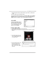
Страница 38: ... biostar com tw 3 Open BIOS Update Utility and click the Update BIOS button on the main screen 4 A warning message will show up to request your agreement to start the BIOS update Click OK to start the update procedure 5 Choose the location for your BIOS file in the system Please select the proper BIOS file and then click on Open It will take several minutes please be patient 6 After the BIOS Updat...

Страница 39: ...eted Backup BIOS Click the Backup BIOS button on the main screen for the backup of BIOS and select a proper location for your backup BIOS file in the system and click Save 2 Online Update Utility 1 Installing BIOS Update Utility from the DVD Driver 2 Please make sure the system is connected to the internet before using this function 3 Open BIOS Update Utility and click the Online Update button on ...

Страница 40: ...oceed 7 After the updating process is finished you will be asked you to reboot the system Click OK to reboot 8 While the system boots up and the full screen logo shows up press Delete key to enter BIOS setup After entering the BIOS setup please go to the Save Exit using the Restore Defaults function to load Optimized Defaults and select Save Changes and Reset to restart the computer Then the BIOS ...

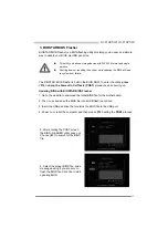
Страница 41: ...ress F12 during the Power On Self Tests POST procedure while booting up Updating BIOS with BIOSTAR BIOS Flasher 1 Go to the website to download the latest BIOS file for the motherboard 2 Then copy and save the BIOS file into a USB flash pen drive 3 Insert the USB pen drive that contains the BIOS file to the USB port 4 Power on or reset the computer and then press F12 during the POST process 5 Afte...

Страница 42: ... Save Exit using the Restore Defaults function to load Optimized Defaults and select Save Changes and Reset to restart the computer Then the BIOS Update is completed All the information and content above about software are subject to be changed without notice For better performance the software is being continuously updated The information and pictures described above are for your reference only T...

Страница 43: ...Driver Installation To install the driver please click on the Driver icon The setup guide will list the compatible driver for your motherboard and operating system Click on each device driver to launch the installation program B Software Installation To install the software please click on the Software icon The setup guide will list the software available for your system click on each software tit...

Страница 44: ...ot power on again In this case please double check 1 The CPU cooler surface is placed evenly with the CPU surface 2 CPU fan is rotated normally 3 CPU fan speed is fulfilling with the CPU speed After confirmed please follow steps below to relief the CPU protection function 1 Remove the power cord from power supply for seconds 2 Wait for seconds 3 Plug in the power cord and boot up the system Or you...

Страница 45: ...U post memory initialization Cache initialization 34 CPU post memory initialization Application Processor s AP initialization 35 CPU post memory initialization Boot Strap Processor BSP selection 36 CPU post memory initialization System Management Mode SMM initialization 37 Post Memory North Bridge initialization is started 3B Post Memory North Bridge initialization North Bridge module specific 4F ...

Страница 46: ...urces 96 PCI Bus Assign Resources 97 Console Output devices connect 98 Console input devices connect 99 Super IO Initialization 9A USB initialization is started 9B USB Reset 9C USB Detect 9D USB Enable A0 IDE initialization is started A1 IDE Reset A2 IDE Detect A3 IDE Enable A4 SCSI initialization is started A5 SCSI Reset A6 SCSI Detect A7 SCSI Enable A8 Setup Verifying Password A9 Start of Setup ...

Страница 47: ...isk to disk controller board Make sure both ends are securely plugged in check the drive type in the standard CMOS setup 2 Backing up the hard drive is extremely important All hard disks are capable of breaking down at any time System only boots from an optical drive Hard disks can be read applications can be used but system fails to boot from a hard disk 1 Back up data and applications files 2 Re...

Страница 48: ...10 دى إم اﻳﻪ AMD A75 FCH وﺻﻠﺔ 6 x ﺳﺎﺗﺎ SATA 3 ﺑﺎﻳﺖ ﺟﻴﺠﺎ اﻟﺜﺎﻧﻴﺔ راﻳﺪ ﺗﺘﺤﻤﻞ RAID 0 1 10 ﻣﺤﻠﻴﺔ ﺷﺒﻜﺔ LAN ل رت رﻳﻴﺎﻟﺘﻴﻚ RTL 8111 F REALTEK 10 100 1000 ﻣﻴﺠﺎﺑﺎﻳﺖ ﺗﻠﻘ ﺗﺤﺪﻳﺪ اﻟﺜﺎﻧﻴﺔ اﻟﻨﺼﻒ ﺎﺋﻲ اﻟﻤﺰدوﺟﺔ اﻟﻘﺼﻮى اﻟﻘﺪرة اﻟﺼﻮﺗﻲ اﻟﺘﺮﻣﻴﺰ ALC892 7 1 اﻟﺪﻗﺔ ﻋﺎﻟﻴﺔ ﻗﻨﻮات Biostar Hi Fi ﻋﺎم ﻣﺘﺴﻠﺴﻞ ﻧﺎﻗﻞ USB ﻣﻨﺎﻓﺬ 4 x ﻋﺎم ﻣﺘﺴﻠﺴﻞ ﻧﺎﻗﻞ USB 3 0 2 و اﻟﺨﻠﻔﻴﺔ واﻟﻤﺨﺎرج اﻟﻤﺪاﺧﻞ ﻓﻲ 2 اﻟﺪاﺧﻠﻲ اﻟﻤﻮزع ﺧﻼل ﻣﻦ ﻣﻨﺎﻓﺬ 8 x ﻋﺎم ﻣﺘﺴﻠﺴﻞ ﻧﺎﻗﻞ...

Страница 49: ... ﻓﻴﻠﻴﺒﺲ ﺳﻮﻧﻲ اﻟﺮﻗﻤﻴﺔ W 75 A Fi Hi وﺻﻠﺔ 6 x SATA 6 ﺟﻴﺠﺎﺑﺎﻳﺖ اﻟﺜﺎﻧﻴﺔ ﻣﻮزع 2 x ﻋ ﻣﺘﺴﻠﺴﻞ ﻧﺎﻗﻞ ﺎم USB 2 0 ﻳﺘﺤﻤﻞ ﻣﻮزع آﻞ ﻋﺎم ﻣﺘﺴﻠﺴﻞ ﻧﺎﻗﻞ ﻓﺘﺤﺘﻴﻦ USB 2 0 ﻣﻮزع 1 x ﻋﺎم ﻣﺘﺴﻠﺴﻞ ﻧﺎﻗﻞ USB 3 0 ﻳﺘﺤﻤﻞ ﻣﻮزع آﻞ ﻋﺎم ﻣﺘﺴﻠﺴﻞ ﻧﺎﻗﻞ ﻓﺘﺤﺘﻴﻦ USB 3 0 ﻟﻠﻄﺎﻗﺔ وﺻﻠﺔ 1 x 4 دﺑﺎﺑﻴﺲ ﻟﻠﻄﺎﻗﺔ وﺻﻠﺔ 1 x 24 دﺑﻮس وﺻﻠﺔ 1 x اﻟﻤﺮآﺰﻳﺔ اﻟﻤﻌﺎﻟﺠﺔ وﺣﺪة ﺗﺒﺮﻳﺪ ﻣﺮوﺣﺔ وﺻﻠﺔ 2 x ﻣ اﻟﻤﻨﻈﻮﻣﺔ ﺗﺒﺮﻳﺪ ﺮاوح ﻣﻮزع 1 x اﻷﻣﺎﻣﻴﺔ اﻟﻠﻮﺣﺔ ﻣﻮزع 1 x اﻷﻣﺎﻣﻲ اﻟﺼﻮت ﻣﻮزع 1...

Страница 50: ...reporter à www biostar com tw pour la liste des soutien de la mémoire Stockage AMD A85 FCH Connecteur 8 x SATA 6Gb s Supporte système RAID 0 1 10 5 AHCI AMD A75 FCH Connecteur 6 x SATA 6Gb s Supporte système RAID 0 1 10 AHCI Réseau local Realtek RTL 8111F 10 100 1000 Mb s auto négociation capacité bidirectionnelle à l alternat bidirectionnelle simultanée Codec audio ALC892 Canaux 7 1 écoute audio ...

Страница 51: ...rie 1x Connecteur sortie S PDIF Hi Fi A75W 6x Connecteur SATA 6 0Gb s 2x embases USB 2 0 chaque embase supporte 2 Ports USB 2 0 1x embase USB 3 0 chaque embase supporte 2 Ports USB 3 0 1x 4 Broche de carte 1x 24 Broche de carte 1x Connecteur ventilateur unité centrale 2x Connecteur ventilateur système 1x Fiche panneau avant 1x Fiche audio avant 1x Fiche mémoire CMOS vide 1x Fiche Registre d état C...

Страница 52: ...Module Bitte konsultieren Sie www biostar com tw für für Speicherunterstützung Liste Arbeitsspeicher AMD A85 FCH 8x SATA 6Gb Verbindung Unterstützt RAID 0 1 10 5 AHCI AMD A75 FCH 6x SATA 6Gb Verbindung Unterstützt RAID 0 1 10 AHCI LAN Realtek RTL 8111F 10 100 1000 Mb Auto Negotiation Halb Voll Duplex fähig Audio Codec ALC892 7 1 Kanäle HD Audio Biostar Hi Fi USB 4x USB 3 0 Port 2 hintere I Os und ...

Страница 53: ...eller Port Header 1x S PDI Auswurfsverbindung Hi Fi A75W 6x SATA 6 0Gb s Verbinung 2x USB 2 0 Header jeder Header unterstützt 2 USB 2 0 Ports 1x USB 3 0 Header jeder Header unterstützt 2 USB 3 0 Ports 1x 4 Pin Stromverbindung 1x 24 Pin Stromverbindung 1x CPU Ventilatorverbindung 2x System Ventilatorverbindung 1x Header für Frontpanel 1x Header für Frontaudio 1x Header für klares CMOS 1x Consumer I...

Страница 54: ...iostar com tw per la lista di supporto del memoria Memorizzazione AMD A85 FCH Connettore 8x SATA 6Gb s Supporta RAID 0 1 10 5 AHCI AMD A75 FCH Connettore 6x SATA 6Gb s Supporta RAID 0 1 10 AHCI Catena Realtek RTL 8111F 10 100 1000 Mb auto negoziazione capacita di duplex Meta Completo Codec Audio ALC892 Canali Audio di Alta Definizione 7 1 Biostar Hi Fi USB Slot 4x USB 3 0 2 nei ingressi uscite pos...

Страница 55: ...erie x1 Connettore esterno S PDIF x1 Hi Fi A75W Connettore 6x SATA 6 0Gb s Distributore 2x USB 2 0 ogni distributore supporta 2 slot USB 2 0 Distributore 1x USB 3 0 ogni distributore supporta 2 slot USB 3 0 Connettore con 4 pin x1 Connettore con 24 pin x1 Connettore Ventilatore processore x1 Connettore Ventilatore Sistema x2 Distributore Pannello Frontale x1 Distributore Audio Frontale x1 Distribu...

Страница 56: ...ルをサポートしています サポートされているメモリのリストについては www biostar com twを参照してください 保存スペース AMD A85 FCH 8x SATA 6Gb s コネクタ RAID 0 1 10 5 AHCI のサポート AMD A75 FCH 6x SATA 6Gb s コネクタ RAID 0 1 10 AHCI のサポート LAN Realtek RTL 8111F 10 100 1000 Mb s オートネゴーシエーション 半 全 二重通信 オーディオ コーデッ ク ALC892 7 1 チャンネル ハイ デフィニション オーディオ Biostar Hi Fi USB 4x USB 3 0 ポート 後部 I O に2つ 及び 内蔵 ヘッダー経由に2つ 8x USB 2 0 ポート 後部 I O に4つ 及び 内蔵ヘッダー経由に4つ 拡張スロット 2x PC...

Страница 57: ... CMOS ヘッダー 1x コンシューマー IR ヘッダー 1x シリアル ポート ヘッダー 1x S PDIF アウト コネクタ Hi Fi A75W 6x SATA 6 0Gb s コネクタ 2x USB 2 0 ヘッダー 各ヘッダーは 2つの USB 2 0 ポートをサポートしています 1x USB 3 0 ヘッダー 各ヘッダーは 2つの USB 3 0 ポートをサポートしています 1x 4 Pin パワー コネクタ 1x 24 Pin パワー コネクタ 1x CPU ファン コネクタ 2x システム ファン コネクタ 1x フロント パネル ヘッダー 1x フロント オーディオ ヘッダー 1x クリア CMOS ヘッダー 1x コンシューマー IR ヘッダー 1x シリアル ポート ヘッダー 1x S PDIF アウト コネクタ フォーム ファクタ ATX フォーム ファクタ 30...

Страница 58: ...ę obsługiwanych pamięć na stronie internetowej www biostar com tw Przechowywanie AMD A85 FCH Złącze 8x SATA 6Gb s Obsługa RAID 0 1 10 5 AHCI AMD A75 FCH Złącze 6x SATA 6Gb s Obsługa RAID 0 1 10 AHCI LAN Układ RTL 8111F 10 100 1000 Mb auto negocjacja pojemność dupleks Połowe Pełny Codec Audio ALC892 Kanały Audio wysokiej Definicji 7 1 Biostar Hi Fi USB 4 x złącza USB 3 0 2 przez tylne porty wejścia...

Страница 59: ...ent IR x1 Port szeregowy x1 Port zewnętrzny S PDIF x1 Hi Fi A75W Złącza 6x SATA 6 0Gb s Złącza 2x USB 2 0 każde złącze obsługuje dodatkowe 2 porty USB 2 0 Złącze 1x USB 3 0 każde złącze obsługuje dodatkowe 2 porty USB 3 0 Złącza 4 pionowe x 1 Złącza 24 pionowe x 1 Złącze wentylatora CPU x 1 Złącze wentylatora obudowy x 2 Złącze przedniego panelu x1 Złącze audio przedniego panelu x1 Złącze bezpośre...

Страница 60: ...ara obter uma lista de suporte do memória Armazenamento AMD A85 FCH Conector 8x SATA 6Gb s Suporta RAID 0 1 10 5 AHCI AMD A75 FCH Conector 6x SATA 6Gb s Suporta RAID 0 1 10 AHCI LAN Realtek RTL 8111F 10 100 1000 Mb auto negociação capacidade duplex Metade Cheio Codec de Audio ALC892 Canais de Áudio de Alta Definição 7 1 Biostar Hi Fi USB Porta 4x USB 3 0 2 nas entradas saídas traseiras e 2 pelos D...

Страница 61: ...rta Série x1 Conector Externo S PDIF x1 Hi Fi A75W Conector 6x SATA 6 0Gb s Dispositivo 2x USB 2 0 cada Dispositivo suporta 2 portas USB 2 0 Dispositivo 1x USB 3 0 cada Dispositivo suporta 2 portas USB 3 0 Conector de 4 pinos x1 Conector de 24 pinos x1 Conector de Ventoinha processador x1 Conector de Ventoinha Sistema x1 Dispositivo Painel Frontal x1 Dispositivo de Audio Frontal x1 Dispositivo CMO...

Страница 62: ...яти смотрите на www biostar com tw Накопитель AMD A85 FCH Соединитель 8x SATA 6 Гб с Поддерживает RAID 0 1 10 5 AHCI AMD A75 FCH Соединитель 6x SATA 6 Гб с Поддерживает RAID 0 1 10 AHCI Локальная сеть Realtek RTL 8111F Автосогласование 10 100 1000 Мб с работает в полно полудуплексном режиме Аудиокодек ALC892 Каналы 7 1 высококачественное аудио Biostar Hi Fi USB 4 порта USB 3 0 2 сзади ввода вывода...

Страница 63: ...ледовательного порта 1 соединитель S PDIF Out Hi Fi A75W Соединитель 6x SATA 6 Гб с 2 контакта USB 2 0 каждый контакт поддерживает 2 порта USB 2 0 1 контакт USB 3 0 каждый контакт поддерживает 2 порта USB 3 0 1 4 выводный разъем питания 1 24 выводный разъем питания 1 разъем вентилятора ЦП 2 разъема вентилятора системы 1 контакт передней панели 1 контакт передней аудиопанели 1 контакт микросхемы Cl...

Страница 64: ...ara la lista de compatibilidad con el memoria Almacenamiento de información AMD A85 FCH Conector 8x SATA 6Gb s Soporta RAID 0 1 10 5 AHCI AMD A75 FCH Conector 6x SATA 6Gb s Soporta RAID 0 1 10 AHCI LAN Realtek RTL 8111F 10 100 1000 Mb s auto negociación capacidad dúplex Mitad Completo Códec Audio ALC892 Canales Audio de Alta Definición 7 1 Biostar Hi Fi USB Ranura 4x USB 3 0 2 en las entrada salid...

Страница 65: ...a Serie x1 Conector Externo S PDIF x1 Hi Fi A75W Conector 6x SATA 6Gb s Distribuidor 2x USB 2 0 cada distribuidor soporta 2 ranuras USB 2 0 Distribuidor 1x USB 3 0 cada distribuidor soporta 2 ranuras USB 3 0 Conector con 4 patillas x1 Conector con 24 patillas x1 Conector Ventilador procesador x1 Conector Ventilador Sistema x2 Distribuidor Panel Frontal x1 Distribuidor Audio Frontal x1 Distribuidor...

Отзывы: