BIO-MICROBICS HighStrengthFAST 4.5 Скачать руководство пользователя страница 17

14 

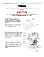
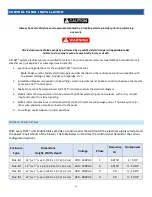
CONTROL PANEL INSTALLATION 


Always have all utility lines and equipment marked by a locating service provider prior to performing 

any work.  


All electrical work shall be properly performed by a qualified electrician per all applicable codes. 

Failure to do so may result in severe bodily injury or death.  


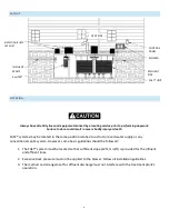
All FAST® system electrical parts are certified for safety. The control panel enclosures meet NEMA4X standards for all-

weather use (not explosive or submerged environments). 
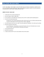
1.


Examine wiring directions for the supplied FAST® control panel.  

Note:

 Make sure the facility electrical supply matches the label on the control panel and is compatible with 

the blower (voltage, phase, frequency, amperage, etc.).


2.


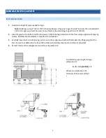
A dedicated breaker is required in the building’s master electrical panel. Make connections between the master 

panel and FAST® control panel. 

3.


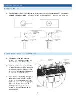
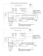
Make connections between blower and FAST® control panel per the electrical diagram.  

4.


BioMicrobics control panels can also be used with optional external inputs and outputs, such as dry contact 

input and output for alarm signaling. 

5.


BioMicrobics manufactures control panels that control UV systems and sewage pumps. The track system (or 

other auto-dialer) can also be connected to the panel. 

6.


For voltage, see ETL label on control panel box. 


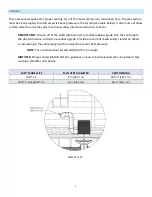
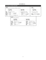
CONTROL PANEL DETAILS 


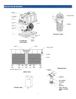
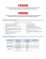
With every FAST® unit, BioMicrobics provides a control panel that will match the electrical supply selected and 

the power requirements of the blower. The table below summarizes the control panel details for the various 

configuration options. 


Enclosure 

Type 

Dimensions 

Height, Width, Depth 


Voltage 

Phase 

Frequency 

Hz


Horsepower 

Box-lid 

14 

1

/

8

 x 7 

7

/

8

 x 6 in [35.9 x 19.7 x 15.2 cm] 

200 - 240VAC 

60/50 

2 - 5 HP 

Box-lid 

14 

1

/

8

 x 7 

7

/

8


x 6 in [35.9 x 19.7 x 15.2 cm] 

200 - 240VAC 

60/50 

½ - 10 HP 

Box-lid 

14 

1

/

8

 x 7 

7

/

8

 x 6 in [35.9 x 19.7 x 15.2 cm] 

380 - 400VAC 

50 

½ - 10 HP 

Box-lid 

14 

1

/

8

 x 7 

7

/

8

 x 6 in [35.9 x 19.7 x 15.2 cm] 

460 - 480VAC 

60 

½ - 10 HP 

Содержание HighStrengthFAST 4.5

Страница 1: ...0 r Installation Manual For use with MicroFAST 4 5 9 0 HighStrengthFAST 4 5 9 0 NitriFAST 4 5 9 0 MyFAST 1 0 Installation Manual FASTIM 002 REV 30 JUN 2022...

Страница 2: ...1...

Страница 3: ...ATION 7 CROSS BRACE 7 COMPONENT INSTALLATION 8 BLOWER AIR SUPPLY LINE 8 SECURING RECYCLE TROUGHS AND BLOWER AIR LINES 8 VENTING 9 BLOWER INSTALLATION 10 BLOWER WIRING DIAGRAM 11 1 AND 3 PHASE BLOWER W...

Страница 4: ...wo components the treatment module and blower The blower provides air to the system via the air supply pipe The air supply pipe and draft tube create an airlift which mixes oxygen and waste throughout...

Страница 5: ...3 REMOTE MOUNTED BLOWER The blower must be set in a dry stable place and its elevation must be higher than the normal flood level A two piece rectangular housing is included with the unit The dischar...

Страница 6: ...LINER GASKET BAFFLE PLATE MEDIA LINER MODULE AIRLIFT TOP DIVERTER SCREEN OPTIONAL SaniTEE MIN ANCHOR WEDGES STAINLESS STEEL FOOT BOTTOM PVC PIPE NOT INCLUDED FOOT TOP 4 SCREWS BLOWER DOWNLIFT PIPE BLO...

Страница 7: ...onal septic system However some basic guidelines should be followed 1 The FAST system must be located so that sufficient slope 2 in ft is provided for the influent and effluent lines 2 Excessive back...

Страница 8: ...ove the FAST unit 3 Anchor wedges stainless steel for securing FAST unit to the tank and blower housing to the base 4 Piping for observation vent port air lines vent lines and leg extensions 5 PVC pip...

Страница 9: ...Attach the leg extensions to the liner using supplied self tapping screws Stainless Steel hardware is required for installation 3 Carefully lower liner into tank using a jib crane or other approved m...

Страница 10: ...er gasket until it hits the baffle plate Use a gasket grout mortar or bituminous sealant mastic in the tank effluent hole for a watertight seal between hole and effluent pipe CROSS BRACE 1 Use the sup...

Страница 11: ...ST 1 0 The recycle troughs for this unit ship loose inside the liner 2 Insert each of the four recycle troughs through the hole in the liner Attach the recycle trough with its mounting point on the ai...

Страница 12: ...iser or manhole below grade Run the vent pipe to the desired location and terminate above grade Provide a cover that meets safety standards Water accumulating in the vent piping must be drained to pre...

Страница 13: ...pad using 4 supplied 14 x 1 self tapping screws Drill screws directly into blower pad 3 Connect initial blower fittings right 4 Connect airline from FAST unit to blower outlet using required piping W...

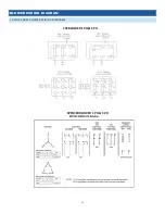
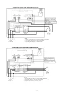
Страница 14: ...11 BLOWER WIRING DIAGRAM 1 AND 3 PHASE BLOWER WIRING DIAGRAMS FPZ BLOWER 1 PH 3 PH SPENCER BLOWER 1 PH 3 PH...

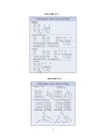
Страница 15: ...12 FUJI BLOWER 1 PH FUJI BLOWER 3 PH...

Страница 16: ...13 GAST BLOWER 1 PH...

Страница 17: ...n blower and FAST control panel per the electrical diagram 4 BioMicrobics control panels can also be used with optional external inputs and outputs such as dry contact input and output for alarm signa...

Страница 18: ...d blower based on the electrical diagram supplied for each panel specifically Note The overload amperage setting supplied for a given motor size is pre set to the appropriate place at the factory and...

Страница 19: ...16 3PH 208V 240V 1PH 208V 240V 3PH 460V...

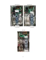
Страница 20: ...17 CONTROL PANEL SCHEMATICS...

Страница 21: ...18...

Страница 22: ...19...

Страница 23: ...20...

Страница 24: ...ration of the air lift A robust splash should be present 4 Check for excessive back pressure Seal all access covers place hand about 8 in 20 cm from FAST vent If you feel air flow then there is excess...

Страница 25: ...ost of labor and all other expenses resulting from replacement of the defective parts and from installation of parts furnished under this warranty shall be borne by the owner This warranty does not co...

Страница 26: ...DATE __________________________________________________________________ SYSTEM DESIGNER __________________________________________________________________ SYSTEM INSTALLER ___________________________...

Отзывы: