


8
COMPONENT INSTALLATION
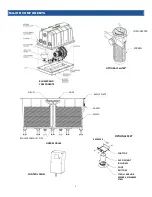
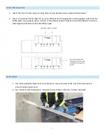
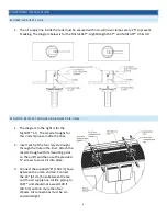
BLOWER AIR SUPPLY LINE
1.
The air supply line inside the tank must be secured with non-corrosive clamps every 2 ft to prevent
breaking. The diagram below is for the MicroFAST®, HighStrengthFAST®, and NitriFAST® 4.5 & 9.0.
SECURING RECYCLE TROUGHS AND BLOWER AIR LINES
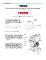
1.
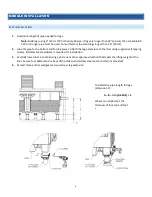
The diagram to the right is for the
MyFAST® 1.0. The recycle troughs for
this unit ship loose inside the liner.
2.
Insert each of the four recycle troughs
through the hole in the liner. Attach the
recycle trough with its mounting point
on the airlift and then use the provided
¾” screws to secure it into place.
3.
Connect the supplied 78” [198 cm] hose
between the union and tee. Connect
the 24” [61 cm] hose between the tee
and the air supply line. Airline piping to
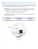
FAST® unit should not exceed 100 ft
[30.5 m] with no more than four
elbows. All connections must be air-
and watertight.
Содержание HighStrengthFAST 4.5
Страница 2: ...1...
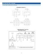
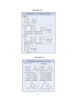
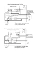
Страница 14: ...11 BLOWER WIRING DIAGRAM 1 AND 3 PHASE BLOWER WIRING DIAGRAMS FPZ BLOWER 1 PH 3 PH SPENCER BLOWER 1 PH 3 PH...
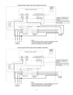
Страница 15: ...12 FUJI BLOWER 1 PH FUJI BLOWER 3 PH...
Страница 16: ...13 GAST BLOWER 1 PH...
Страница 19: ...16 3PH 208V 240V 1PH 208V 240V 3PH 460V...
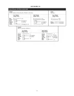
Страница 20: ...17 CONTROL PANEL SCHEMATICS...
Страница 21: ...18...
Страница 22: ...19...
Страница 23: ...20...


