


SETUP FOR SPRAYING
CONNECTING GUN TO MATERIAL HOSE
Gun should be connected by a suitable length of 3/8"
diameter material hose fitted with a connector with a
3/8" NPS(f) nut at gun end. 1/4" diameter hose is
recommended for use with low viscosity materials.
(Fluid hoses of different composition are available for
special fluids.)
CONNECTING GUN TO ATOMIZING AIR
Gun should be connected by a suitable length of 5/16"
or 3/8" diameter air hose fitted with a connector and a
1/4" NPS(f) nut at gun end.
CONNECTING GUN TO CYLINDER AIR
Gun should be connected by a suitable length of 3/16"
I.D. or 1/8" I.D. air hose of shortest length possible
with 1/4" NPS(f) connector.
OPERATING THE MACH 1AR HVLP AUTOMATIC SPRAY GUN
CONTROLLING THE MATERIAL FLOW
When fed from a pressure supply, an increase in the
material pressure will increase the rate of flow. Correct
fluid nozzle size ensures correct material flow rate. If
necessary, fluid flow can also be adjusted by adjusting
the amount of needle travel. This is done by adjusting
the ratchet housing cap (35) until the correct needle
travel is achieved.
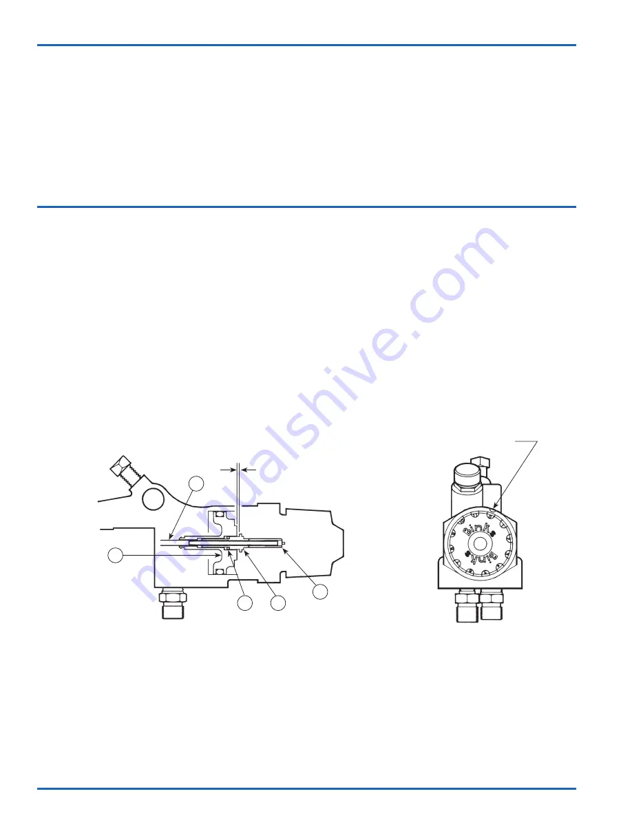
ADJUSTING AIR AND FLUID TIMING
A 1/16" gap between the air piston assembly (18) and
needle body (24) should be maintained (see figure 1).
This will create needle motion that will allow adequate
air flow before the fluid starts flowing. The gap may be
adjusted by partially removing the material needle (22),
screwing it either in or out of the needle body (24) and
locking it back into the gun while being sure to check
the clearance between the air valve piston (18) and the
needle body (24).
ADJUSTING THE SPRAY PATTERN
The width of the spray pattern is controlled by the side
port control assembly (7). (See page 6). Turning this
control clockwise until it is closed will give a round
spray; turning it counterclockwise will widen the spray
into a fan shape. The fan spray can be turned
anywhere through 360
°
by positioning the air nozzle
(2) relative to the gun. To effect this: loosen retaining
ring (1); position nozzle (2) then retighten
retaining ring.
Indicator notch
Rear
View
Figure 1
1/16" clearance
20
22
23
24
25
RATCHET ADJUSTMENT
1. First, note the number on the indicator notch (see
REAR VIEW above).
2. Remove ratchet housing assembly (28) and 2 springs
(26 & 27). Make sure needle body (24) is set with a
1/16" clearance as shown in figure 1. (To set 1/16"
clearance, see “ADJUSTING AIR AND FLUID TIMING”
above).
3. Remove screw (33) from inside the center of the
ratchet housing (29) and pull off cap (35).
4. Reset cap back onto ratchet housing assembly (28)
aligning the zero on the cap to the indicator notch
as shown in the REAR VIEW above.
5. Tighten screw (33) and reassemble springs and
ratchet housing assembly to gun. The needle should
now be closed and in the zero position.
NOTE:
All No’s. in parenthesis refer to Item No’s. in Assembly Drawing on Page 6.
EN
77-2672-R7.0 (8/2017)
8 / 16
www.carlisleft.com