Binks A12846 Series Скачать руководство пользователя страница 1

IMPORTANT:  Before using this equipment, 
carefully read SAFETY PRECAUTIONS, starting on 
page 1, and all instructions in this manual.  Keep 
this Service Manual for future reference.   
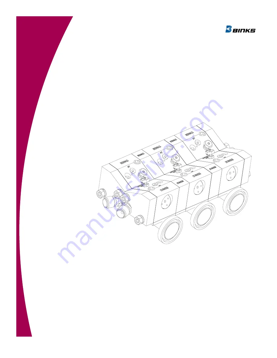
MODEL: A12846-XX 

PRODUCT MANUAL 

CS-11-02.1 

Inline/Piggable   

Dual Modular Color Changer 


Product Manual Price:  $50.00 

Содержание A12846 Series

Страница 1: ...efully read SAFETY PRECAUTIONS starting on page 1 and all instructions in this manual Keep this Service Manual for future reference MODEL A12846 XX PRODUCT MANUAL CS 11 02 1 Inline Piggable Dual Modular Color Changer Product Manual Price 50 00 ...

Страница 2: ...2 CS 11 02 1 Inline Piggable Dual Modular Color Changer ...

Страница 3: ... Section 3 INSTALLATION 18 19 Color Changer Installation Procedures Section 4 OPERATION 20 22 Color Changer Schematics Grounding of the Color Changers Fluid Inlet and Outlet Fittings Air Pilot Hose Fluid Output Hose Assembly with Purge Block Assembly with No Purge Block Section 5 MAINTENANCE 23 27 Micro Valve and Valve Seat Replacement Test and Checkout Procedure for Color Changer Tools and Option...

Страница 4: ...4 CS 11 02 1 Inline Piggable Dual Modular Color Changer ...

Страница 5: ...are this manual with your system installation drawings and appropriate Ransburg equipment manuals to reconcile such differences Careful study and continued use of this manual will provide a better understanding of the equipment and process resulting in more efficient operation longer trouble free service and faster easier troubleshooting If you do not have the manu als and safety literature for yo...

Страница 6: ...ge supplied to the atomizer must be turned off prior to cleaning flushing or maintenance When using solvents for cleaning Those used for equipment flushing should have flash points equal to or higher than those of the coating material Those used for general cleaning must have flash points above 100 F 37 8 C Spray booth ventilation must be kept at the rates re quired by NFPA 33 2009 Edition OSHA an...

Страница 7: ...em with the system which requires correction Always turn the control panel off prior to flushing clean ing or working on spray system equipment Ensure that the control panel is interlocked with the ventilation system and conveyor in accordance with NFPA 33 2009 Edition Have fire extinguishing equipment readily available and tested periodically Explosion Incompatible Materials Halogenated hydrocarb...

Страница 8: ...ontrol equipment must NOT be used in Class I Division 1 or 2 locations Electrical Discharge High voltage equipment is utilized Arcing in areas of flammable or combustible mate rials may occur Personnel are exposed to high voltage during operation and mainte nance Protection against inadvertent arcing that may cause a fire or explosion is lost if safety circuits are disabled during operation Freque...

Страница 9: ...el must be given training in accordance with the requirements of NFPA 33 2009 Edition Instructions and safety precautions must understood prior to using this equipment Comply with appropriate codes governing ventilation fire protection operation maintenance and housekeep ing OSHA references are sections 1910 94 and 1910 107 Also refer to NFPA 33 2009 Edition and your insurance company requirements...

Страница 10: ... See Color Changer Schematics in the Operation section Valve Block Assembly Weight Dual Valve Assembly 45 lbs 204 1 grams Assembly Weight with 3 4 Tube Dual Valve Assembly 1 75 lbs 793 8 Kg Purge Block Assembly Weight 96 lbs 435 4 grams Spacer Block Weight 936 Block 20 lbs 90 7 grams 437 Block 09 lbs 40 8 grams Spacer Plate Weight 936 Spacer Plate 08 lbs 36 3 grams 437 Spacer Plate 04 lbs 18 1 gra...

Страница 11: ...EERED COLOR CHANGER ASSEMBLIES The following is for Pre Engineered Color Changer assemblies Please reference selection chart for the changer as sembly number 14 6 21 20 8 7 2 22 6 11 9 24 25 15 1 4 17 19 3 5 9 11 6 28 27 SHOWN WITH PURGE BLOCK ASSEMBLIES INSTALLED 73 ...

Страница 12: ...k Assembly Dual 13 Table A Item A A12727 00 Shut off Valve Assembly 14 Table A Item B Table B Item J Spacer Block 1 5 15 Table C Item N 78079 00 Ftg 7 16 20 X 3 8 NPS 17 Table B Item F A12772 01 Screw 10 24 X 1 2 Stainless SHCS 19 Table A Item B Table B Item K Spacer Plate Dual 20 Table A Item A A12766 02 Screw SHCS 5 16 18 SS 21 Table A Item A A12766 01 Screw SHCS 5 16 18 SS 22 Table B Item G A12...

Страница 13: ...ber of Color Blocks 22 11 20 24 12 Number of Color Blocks 24 12 22 26 13 Number of Color Blocks 26 13 24 28 14 Number of Color Blocks 28 14 26 30 15 Number of Color Blocks 30 15 28 32 16 Number of Color Blocks 32 16 30 34 17 Number of Color Blocks 34 17 32 36 18 Number of Color Blocks 36 18 34 38 19 Number of Color Blocks 38 19 36 40 20 Number of Color Blocks 40 20 38 42 21 Number of Color Blocks ...

Страница 14: ...s 02 3 4 Standard A12845 02 0 1 91 2 12 X Number of Colors Pipe Assemblies will be on 2 1 16 Centers 03 1 Standard A12845 03 4 A12742 00 A12856 00 1 91 3 06 X Number of Colors Pipe Assemblies will be on 3 Centers 04 1 1 2 Standard A12845 04 4 A12742 00 A12856 00 1 91 3 06 X Number of Colors Pipe Assemblies will be on 3 Centers 05 1 2 Standard A12845 01 4 A12861 00 A12883 00 1 91 2 48 X Number of C...

Страница 15: ...ock 2 2 77367 00 Valve Seat Assembly 3 2 78949 00 Valve Assembly 4 2 A12727 00 Shut off Valve Assembly 5 2 79001 30 O Ring Solvent Proof 6 2 77516 04 Collet 4mm 7 2 79001 06 O Ring Solvent Proof 8 1 A12829 00 Purge Block End Plate Assembly 9 2 78079 00 Ftg 7 16 20 X 3 8 NPA Torque to 15 20 lbs in after valve is down Torque to 15 20 lbs in 1 7 2 3 Nm Torque to 30 lbs ft 40 67 Nm 4 Apply A11545 00 P...

Страница 16: ... Repairable 4 2 77367 00 Valve Seat Assembly 5 1 A12849 00 Inlet Block Assembly Left Dual 6 2 79001 06 O Ring Solvent Proof 7 2 78079 00 Ftg 7 16 20 X 3 8 NPS 8 2 A12727 00 Shut off Valve Assembly 9 2 79001 30 O Ring Solvent Proof 10 2 77516 00 Collet 4mm 11 1 A12855 00 Purge Block Left Dual Torque to 15 20 lbs in after valve is down 1 7 2 3 Nm Torque to 15 20 lbs in 1 7 2 3 Nm Torque to 30 lbs ft...

Страница 17: ...17 CS 11 02 1 Inline Piggable Dual Modular Color Changer COLOR CHANGER ASSEMBLY MODEL IDENTIFICATION Continued NOTES ...

Страница 18: ...from airborne paints and solvents Calculate Footprint of Color Changer See Mounting Single Valve Color Changer Figure To calculate the footprint of the color changer add 1 The dimension of the purge assembly if used 2 The dimension s of the color block s used to create the desired number of color valves 3 The dimension of the inlet outlet block Dimension of Purge Assembly 2 60 66 04mm Dimension of...

Страница 19: ...et Block 53 3 13 79 50 2 064 66 04 2 064 66 04 655 16 64 EXAMPLE OF A 2 COLOR UNIT WITH PURGE BLOCK ATTACHED FOR A COMBINATION INCLUDING 1 2 AND 3 4 PIPE SIZE NO SPACER REQUIRED 2 064 52 43 3 75 RETRO FIT APPLICATION FROM EXISTING BINK PCC MODEL 78428 XX FOR 1 AND LARGER PIPE ASSEMBLIES RETRO FIT FROM EXISTING BINKS PCC TO NEW BINKS COLOR CHANGER 1 AND 1 1 2 PIPE SIZE ONLY EXAMPLE OF A 2 COLOR UNI...

Страница 20: ...irected by an authorized Ransburg representative or conducted using the Ransburg installation drawings provided for your particular installation The assembly consists of modules attached to each other Modules may be added or removed from the assembly as desired If for instance the number of required materials increases the assembly can be expanded by adding additional modules Each module can also ...

Страница 21: ...and out of the pipe assemblies have standard sanitary fittings The color changer MUST be properly grounded Proper grounding as described below will prevent static charge build up and possible discharge from the color changer WARNING NOTE IN and OUT hoses CAN be reversed on the color changer AIR PILOT HOSE Each color changer valve requires a 5 32 4mm pilot hose to activate the color valve FLUID OUT...

Страница 22: ... 2 F L O W O F P A I N T COLOR VALVE PILOT 5 32 4MM TUBING PAINT SHUTOFF VALVE COLOR BLOCK REF 1 1 2 PIPE ASSEMBLY WITH COLOR BLOCK REF NOTE Microvalve Weep Holes These holes will give an indication of fluid valve failure In the event of the fluid seal failure paint or solvent will be seen coming out of this hole In the event that the air seal for the piston falls air will be heard or felt coming ...

Страница 23: ... Using the valve removal tool A10756 00 or A11922 00 engage the four 4 pins of the tool into the four 4 pin holes of the valve assembly Turn the assembly counter clockwise until removed 2 Valve Seat Assembly 77367 00 If required to remove the valve seat assembly use the valve seat removal tool A10766 00 turning the valve seat counter clockwise until removed Clean and inspect the valve body and o r...

Страница 24: ...eck for a crisp and sharp actuation of air flow through the output of the 1 ball valve If valve is sluggish repair or replace valve assembly 78949 00 TEST AND CHECK OUT PROCEDURE FOR COLOR CHANGER Continued NEVER wrap the equipment in plastic to keep it clean A surface charge may build up on the plastic surface and discharge to the nearest grounded object Efficiency of the equipment will also be r...

Страница 25: ...ntinued NOTE Microvalve Wee Holes These holes will give an indication of fluid valve failure In the event of the fluid seal failure paint or solvent will be seen coming out of this hole In the event that the air seal for the piston fails air will be heard or felt coming from this hole Valve Testing Assembly ...

Страница 26: ...00 SEAT ASSEMBLY REPLACEMENT PARTS ITEM PART NUMBER DESCRIPTION 1 79001 01 O Ring Solventproof 2 79001 02 O Ring Solventproof 3 79001 04 O Ring Solventproof 77620 00 VALVE PLUG KIT ITEM PART NUMBER DESCRIPTION 1 79244 00 Plug 2 79001 19 O Ring Solventproof 3 79001 14 O Ring Solventproof 4 77618 00 Plug Seat 79001 16 0 RING A12727 00 PAINT SHUTOFF ASSEMBLY ...

Страница 27: ...gable Dual Modular Color Changer RECOMMENDED SPARE PARTS RECOMMENDED SPARE PARTS PART NUMBER DESCRIPTION QTY A12727 00 Shut off Valve Assembly 4 78949 00 Valve Assembly 2 77367 00 Valve Seat Assembly 2 77516 04 Collet 4mm 2 4 ...

Страница 28: ...as a complete unit is one 1 year from date of purchase WRAPPING THE APPLICATOR IN PLASTIC WILL VOID THIS WARRANTY RANSBURG S ONLY OBLIGATION UNDER THIS WARRANTY IS TO REPLACE PARTS THAT HAVE FAILED BE CAUSE OF FAULTY WORKMANSHIP OR MATERIALS THERE ARE NO IMPLIED WARRANTIES NOR WARRAN TIES OF EITHER MERCHANTABILITY OR FITNESS FOR A PARTICULAR PURPOSE RANSBURG S NO LIABIL ITY FOR INJURY DAMAGE TO PR...

Страница 29: ...hnical Service Assistance 320 Phillips Ave Toledo Ohio 43612 1493 Telephone toll free 800 233 3366 Telephone 419 470 2021 Fax 419 470 2040 Technical Support Representatives can direct you to the appropriate telephone number for ordering spare parts 2012 Illinois Tool Works Inc All rights reserved Models and specifications subject to change without notice Form No CS 11 02 1 Litho in U S A 03 12 ...

Отзывы: