DC1-2
SYSTEM INSTALLATION AND START UP
INSTALLATION
INSERT PLUGS AFTER SYSTEM HAS
BEEN FILLED WITH LUBRICANT,
PURGED OF AIR AND READY FOR
OPERATION-SEE “FILLING SYSTEM
WITH LUBRICANT.”
ADD LINE STRAINERS TO RETURN
LINES OF SYSTEMS WITH COMPLETE
LOOPS AND TO DISCHARGE LINES OF
END-OF-LINE SYSTEMS THEY REMOVE
FOREIGN MATTER WHICH MAY BE
ADDED DURING INSTALLATION.
REVERSING VALVE OF SOME
CS2000 & DC42 STATIONS
NEED EXTRA PIPE PLUG. SEE
REVERSING VALVE BULLETINS
DL-1200
ADD 2-WAY LINE CHECKS U-1929B TO
DISCHARGE LINE OF ALL OIL SYSTEMS.
THEY PREVENT LINE DRAINAGE WHILE
SYSTEM IS NOT OPERATING. DO NOT
INSTALL ONE-WAY CHECKS. THEY
BLOCK RELIEF TO RESERVOIR IN IDLE
SUPPLY LINE.
PRESSURE SWITCHES U-620Dl OR
U-663-6 OPERATE SOLENOID RE-
VERSING VALVE & STOP PUMP WHEN
MAX. SYSTEM PRESSURE IS REACHED.
PRESSURE GAUGES
U-902F HELP SET
MAXIMUM SYSTEM
PRESSURE
RESERVOIR
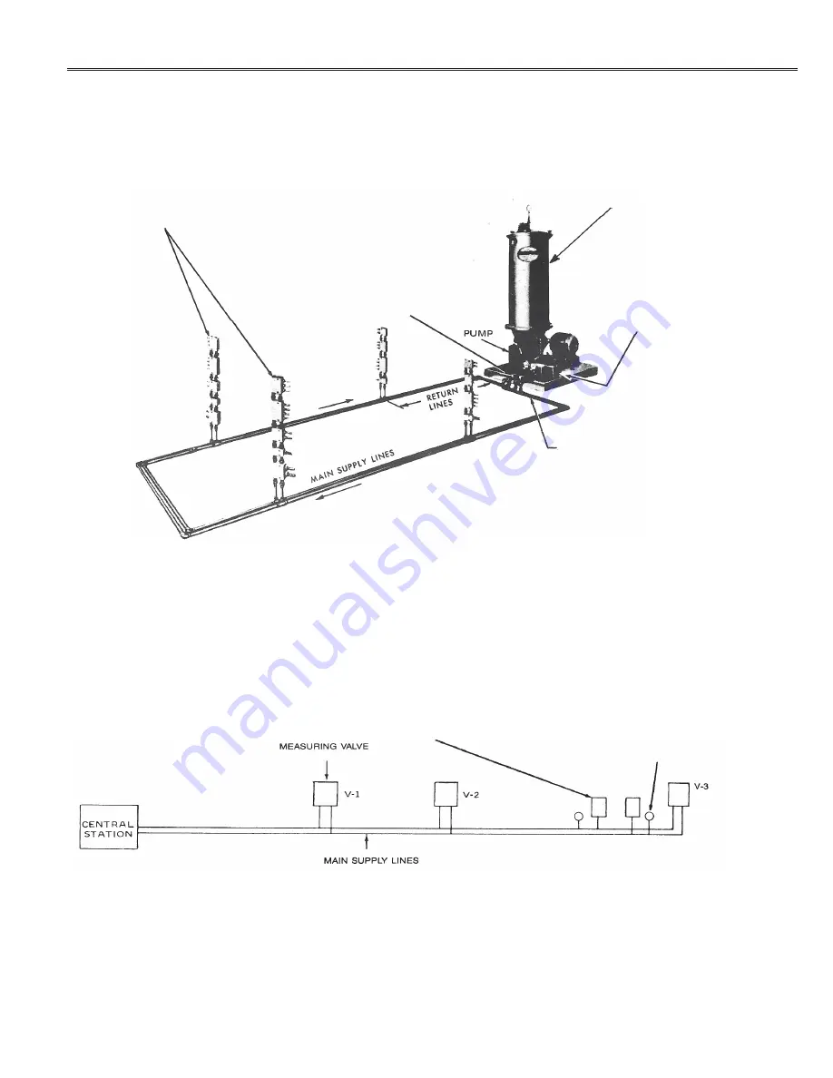
Fig. l-A typical automatic loop system.
Fig. 2-DC41 System showing use of pressure switches.
Pressure Control Switches (End-of-Line Systems with FR Reversing Valves)-Can locate anywhere in the line. If there is
more than one set of main supply lines, install switches in the set with greatest pressure drop (usually the longest) and in others
with pressure drops of similar magnitude. See Fig. 2.
Pressure Gauges (End-of-Line Systems with DR Reversing Valves)-Add pressure gauge U-902F (0-5000 psi) where distribu-
tion line ends at last measuring valve to help adjust system pressure during start up period.
Electric Wiring-Connect motor so that pump rotates as shown in the detail section. If there is more than one set of main supply
lines with pressure control switches, wire. the corresponding switches in each main line in series so that full line pressure devel-
ops throughout system before pump stops. See appropriate controller bulletin for wiring diagram.


