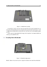
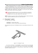
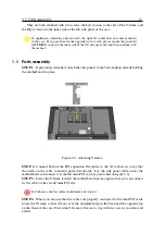
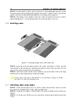
background image

24

Chapter 4. Installation

cat / proc / p a r t i t i o n s

4.1.2

Installing the software to the device

After the USB stick has been prepared with the image, it is time to install the software. For

this you only need the device assembled and its power supply plugged to the wall power
socket.

Before connecting the power jack to the device, plug the USB stick into one of the two

USB connectors at the back of the device, after which you can plug the power into the device.

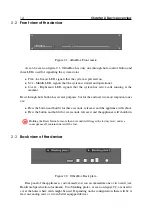
The installation will commence, and you can track its progress via the three LEDs located at

the front of the device.

Right after you plug the power into the device, the P

WR

LED will light up. As the

installation progresses, all three LEDs will light up in a rotating manner to indicate that the
installation procedure is ongoing.

If you encounter all three LEDs blinking at the same time, you have run into a rare case

where there is something already installed on the device. If you wish to overwrite the current

content on the device, use a pin to gently press the R

ESET

button through hole. That will

force the installation to overwrite the content on the device.

After the installation has finished, the P

WR

and S

YS

LEDs will be turned on. When this

happens, the installation is successfully finished, after which you must unplug the power and
the USB stick.
Installation process should take approximately 8 minutes to complete.

4.2

Mounting

The officeBox device can be placed in three basic setups. The device can be mounted prior to

performing the Setup Wizard or it can be mounted later, which really depends on whether the
deployment technician needs an easy access to the backside and the MAN port for network
configuration.

N

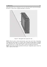
Prior to wall or rack mounting, please unscrew the rubber stand-offs from the bottom of
the device.

4.2.1

Rack mount

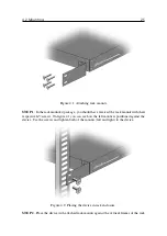
Rack mount step-by-step procedure describes the simplest way to attach the device to the
standard 19-inch rack enclosure via optional rack mounts. Since the device is narrower than
the standard 1U equipment, rack mounts are slightly longer to accommodate the vertical
frames to which the equipment must be fixed. This procedure is divided into three steps and
the deployment technician only needs to decide where to mount the device inside the rack.

Most of the rack enclosures come with front and back vertical frames so you could place

your device wherever you want and thread your cables either from the front or from the back

of the rack. To accommodate all positions and orientations, officeBox side panels come with
symmetrically positioned screw holes, both on the left and the right side. Please observe the
steps.

Содержание OfficeBox Gen. 3

Страница 1: ...OfficeBox Gen 3 HARDWARE MANUAL...

Страница 2: ...ION IS PROVIDED AS IS AND ALL EXPRESS OR IMPLIED CON DITIONS REPRESENTATIONS AND WARRANTIES INCLUDING ANY IMPLIED WARRANTY OF MERCHANTABILITY FITNESS FOR A PARTICULAR PURPOSE OR NONINFRINGEMENT ARE DI...

Страница 3: ...well as information regarding support for this product while under warranty is available to Bicom Systems customers and other parties through the Bicom Systems Support website HTTP WWW BICOMSYSTEMS CO...

Страница 4: ......

Страница 5: ...power supply 8 1 3 3 Electrical shock 8 1 3 4 Equipment modifications 8 1 3 5 Ventilation 8 1 3 6 Placement 9 1 3 7 Regulations and information 9 I Device 2 Device overview 13 2 1 Hardware specificati...

Страница 6: ...rting cards 22 3 7 Attaching other case plates 22 4 Installation 23 4 1 Installing the software image 23 4 1 1 Writing image to USB memory 23 4 1 2 Installing the software to the device 24 4 2 Mountin...

Страница 7: ...used in this document The document will follow a set of conventions which will give it a different emphasis depending on the importance that shown information has Please observe the following W This i...

Страница 8: ...er power system If you are not sure what kind of power system your facility has please contact the facility manager or qualified electrician W Not all power adapters will fit your OfficeBox power supp...

Страница 9: ...hat appliance is stored in a well vented place and no objects are placed on top of it as well as avoiding placing the device on top of other radiating surfaces W Do not put the appliance near a radiat...

Страница 10: ......

Страница 11: ...4 Supported phones 3 Hardware assembly 17 3 1 Case disassembly 3 2 Preparing the motherboard 3 3 Securing the motherboard 3 4 Preparing X1 sockets 3 5 Parts assembly 3 6 Inserting cards 3 7 Attaching...

Страница 12: ......

Страница 13: ...Box is a highly embedded appliance owning its integrated nature to latest technology advancements which in turn guarantees small dimensions minimal number of parts and no moving parts whatsoever This...

Страница 14: ...mportant ones are Press the button and hold it for three seconds release it and the appliance will reboot Press the button and hold it for six seconds release it and the appliance will shutdown W Hold...

Страница 15: ...d Area Network ethernet port used for the manual connection to the appliance which is needed to discover or setup the network details for the LAN port See Section 4 3 RAN Replication Area Network dedi...

Страница 16: ......

Страница 17: ...d Allen key which comes packaged with the appliance These should be enough to work with all the screws in the appliance 3 1 Case disassembly Case disassembly is a pretty straightforward matter and can...

Страница 18: ...1 Unpack both the motherboard and the APU heat sink from the plastic wrapping Use the small double sided sticky tape that came in the heat sink package and center it on the APU on the motherboard As y...

Страница 19: ...ntly pressing downwards until you hear a click Place the second mini PCI card the same way as the first one into the middle 2nd mini PCI slot Lastly insert the 16GB mSATA SSD storage into the rightmos...

Страница 20: ...et it stick to the bottom plate until you have positioned the motherboard so that you can secure it with four screws in the corners STEP 3 When the corner screw holes on the motherboard align with the...

Страница 21: ...herboard in place Figure 3 6 Attaching T frame STEP 2 Connect both of the PCI expansion flat cables to the X1 sockets in a way that the notch on the cable connector point downwards Lay the side panel...

Страница 22: ...he card attached to the T frame side while the procedure for other card is the same it is just placed in the socket attached to the left side panel STEP 2 Attach the cards with the screws wherever you...

Страница 23: ...device 4 1 1 Writing image to USB memory What this step actually achieves is to place the PBXware raw image onto a USB memory stick via a specialized software that does that operation On Windows this...

Страница 24: ...ens the installation is successfully finished after which you must unplug the power and the USB stick Installation process should take approximately 8 minutes to complete 4 2 Mounting The officeBox de...

Страница 25: ...s with their respective M3 screws On figure 4 1 you can see how the left mount is positioned against the device Use the screws and tighten both of the mounts left and right to the device Figure 4 2 Pl...

Страница 26: ...is oriented towards the front or the back of the rack enclosure 4 2 2 Wall mount Mounting the device on the wall is even simpler than rack mounting since there are no problems related to the orientati...

Страница 27: ...ith attached brackets against the vertical surface Depending on whether the vertical surface is a concrete wall or made from other material you might need to drill holes in the surface and place plast...

Страница 28: ...g configuration LAN port DHCP eth0 MAN port DHCP with fallback IP 192 168 100 1 24 eth1 RAN port not configured eth2 will be setup in future implementation of the replica tion component STEP 1 To conn...

Страница 29: ...the current ethernet configuration If you are satisfied with the current configuration write down your LAN IP address and select Exit button If you need to set up a static IP address please select Nex...

Страница 30: ...gure 4 9 Providing static IP details STEP 7 Please provide the static IP details that you wish the LAN port to use and confirm with Next If you do not have any specific routing rules simply skip the n...

Страница 31: ...tup Wizard configuration as will be seen in next chapter W Bicom Systems highly recommends using the static IP address allocation since DHCP based one has a tendency to change in situations with power...

Страница 32: ......

Отзывы: