Page 22
Biasi SG Series
10. Boiler Jacket Assembly
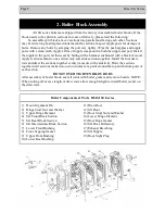
Boiler Components & Parts
Biasi SG — Series
Boiler Jacket Assembly:
1) Boiler Body
2) Insulation Surrounding Boiler
3) Lower Mounting Bracket
4) Upper Mounting Bracket
5) M10 Nut (mounted on tie rod)
6) RH Side Jacket Panel
7) LH Side Jacket Panel
8) Top Jacket Panel
9) Top Rear Jacket Panel*
10) Bottom Rear Jacket Panel*
11) Front Jacket Panel*
12) Control Panel
13) Self-tapping screw
(min. 3/4” long)
14) Self-tapping screw
(min. 1/2” long)
* Supplied with attached insulation
1) Install jacket after installing supply and return piping and installing the breech. After hanging the
jacket, install the immersion well for the aquastat and the PRV piping.
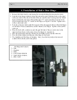
2) Wrap the boiler body (1) with insulation (2) and fasten in
place with strap provided. Secure the plastic strap use
the white plastic buckles (Fig. 10.1) supplied in the
casing box.
3) Attach the two upper mounting brackets (4) to the upper tie rods using the outer nuts (5) already
mounted on tie rods.
4) Attach the two lower mounting brackets (3) to the lower tie rods using the outer nuts (5) already
mounted on the tie rods.
5) Mount side panels (6-7) by sliding slit on bottom of panel onto tab on lower mounting bracket (3)
and fasten to top mounting bracket (4) using washers and self-tapping screws (14).
6) Insert the control panel (12) between side panels (6-7) and fasten to top mounting bracket (4)
through the back of the control panel with the screws supplied (13). Please see next page for
installation location of sensor fittings and probes.
7) Fasten the two rear panels (9-10) to the side panels (6-7) with screws supplied (14).
8) Close top of boiler with the cover (8), hooking it to the sides (6-7) in the front and fastening it in
the rear with screws (14).
9) Attach front panel (11) of the casing by sliding onto tabs located on bottom of the side panels (6-7),
and pushing top of front panel till mounting pins engage.
NOTE: Do not attach any electrical wiring, conduit or boiler piping to the to the front (#11) or top
panel (#8) of the casing.
Fig. 10.1
Содержание SG 2
Страница 2: ...Page 2 Biasi SG Series...
Страница 26: ...Page 26 Biasi SG Series 12 1 Oil Burner Wiring...
Страница 27: ...Biasi SG Series Page 27 12 1 Oil Burner Wiring...
Страница 28: ...Page 28 Biasi SG Series 12 2 Gas Burner Wiring TO EARTH GROUND LINE HONEYWELL 7248U...
Страница 29: ...Biasi SG Series Page 29 12 2 Gas Burner Wiring...
Страница 33: ...Biasi SG Series Page 33 13 4 Efficiency Control Wiring Wiring SG Control Panel with Efficiency Control...
Страница 37: ...Biasi SG Series Page 37 Notes...
Страница 38: ...Page 38 Biasi SG Series Notes...
Страница 39: ...Biasi SG Series Page 39 Notes...

