Biasi Riva Plus Скачать руководство пользователя страница 37


Riva Plus Manual 

37


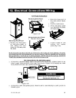
15.1 Initial filling of the system: 

  Remove 

the 

front 

panel of the case. 

  Unscrew  the  cap  on 

the 

automatic 

air 

purger  valve  3  (Fig 
15.1)  one  full  turn  and 
leave 

open 

permanently. 

3

2


Figure 15.1 

  Open 

the 

installer 

supplied  automatic  fill 
valve between the cold 
water  inlet  and  Central 
Heating  System  (See 
28  on  piping  diagrams 
in previous section). 


  Open  each  radiator  air 

vent  starting  at  the 
lower point and close it 
only  when  clear  water, 
free  of  bubbles,  flows 
out. 

  Purge  the  air  from  the 

pump  by  unscrewing 
the  pump  plug  2  (Fig. 
15.2); 

release 

the 

pump  by  turning  the 
rotor  in  the  direction 
indicated  by  the  arrow 
on 

the 

information 

plate. 

2


figura 15.2 

  Close the pump plug. 


  Continue 

filling 

the 

system. 

The 

actual 

reading  should  ideally 
be 1.3 bar (19 psi) and 
not  less  than  0.3  bar 
(4.3 psi). 

  Close  all  air  release 

valves  on  the  c.h. 
system. 

  Inspect  the  boiler  and 

the  system  for  water 
soundness 

and 

remedy 

any 

leaks 

discovered. 

  Cold  flush  the  system 

to  remove  any  loose 
particles 

and 

any 

system  debris  before 
starting  the  boiler  for 
the first time. 

  Reassemble  the  front 

panel of the case. 

  Return  fill  valve  to 

automatic position.


15.2 Lighting the boiler: 


Note: If external controls are fitted (e.g. room thermostat) ensure they "call for heat". 


  Turn on the electricity 

supply  to  the  boiler, 
switching 

on 

the 

circuit breaker switch. 
The 

appliance 

operation  light  A  will 
flash 

every 

seconds. 

  Turn 

the 

function 

selector  B  as  in  Fig. 
15.3.  The  appliance 
operation  light  A  will 
flash 

every 

seconds.  

B

A

C

D


Figure 15.3 

 
The boiler will now go through an ignition sequence and the burner will light. 
If during the ignition attempt period the boiler fails to light, the full sequence control p.c.b. will 
go to lockout and the lock-out signal lamp D will appear. 
To reset the boiler turn the knob B (figure 15.3) on the 0 position and then


press and release 

the boiler reset button C (Fig. 15.3). 

WARNING 

 15. Commissioning 

THE BOILER AND ITS GAS CONNECTION MUST BE LEAK 
TESTED BEFORE THE BOILER IS PLACED IN OPERATION. 

Содержание Riva Plus

Страница 1: ...building Immediately call your gas supplier from a neighbor s phone Follow the gas supplier s instructions If you can not reach your gas supplier call the fire department Installation and service mus...

Страница 2: ...Riva Plus Manual 2...

Страница 3: ...ssfully as those we specify The installing contractor is the best judge of a system s specific requirements as well as the local availability of certain makes and models of controls and accessories Th...

Страница 4: ...he Flue System 9 2 20 Choice of Flue 9 3 21 26 Pipe Connections 10 27 Gas Pipe Connections 11 28 Electrical Connections Wiring 12 Power Connection 12 1 29 Connection to the Electricity Supply 12 2 29...

Страница 5: ...User 15 10 42 Gas Conversion 16 43 Annual Maintenance 17 Warnings 17 1 44 Dismantelling the External Panels 17 2 44 Emptying the C h System 17 3 44 Cleaning the Primary Heat Exch 17 4 44 Checking the...

Страница 6: ...our building Immediately call your gas supplier from a neighbor s phone Follow the gas supplier s instructions If you can not reach your gas supplier call the fire department Installation and service...

Страница 7: ...th those of influenza and the highest incidence of poisoning occurs at the onset of cold weather or during flu season A victim may not experience any symptoms only one symptom or a few symptoms Suspec...

Страница 8: ...n and free of all fire hazards Please read the literature and warranties supplied by the manufacturers of the various accessory equipment This equipment is warranted by the respective manufacturers no...

Страница 9: ...contains an integral frost protection system to prevent frost damage which can occur in areas susceptible to very cold weather conditions Boiler operation recognition system should the boiler not be u...

Страница 10: ...imum Venturi pressure inwc 0 64 Flue pipe diameter Coaxial in 2 25 4 3 25 5 Twin split pipes in 3 25 3 25 Nominal heat flow rate 0 2000ft MBH 116 0 Nominal heat flow rate 2000 4500ft MBH 110 2 in Exha...

Страница 11: ...16 Gas valve inlet pres Test point 17 Central heating expansion vessel 18 Central heating temp Probe NTC 19 Central heating pressure relief valve 20 Primary circuit flow switch 21 Main circuit drain c...

Страница 12: ...Manual 12 14 4 15 16 7 9 11 27 3 1 18 20 22 21 19 17 24 15 4 Internal Piping Parts List Note Pressure Relief Valve 19 should be piped to a drain or to the floor as lose as possible to a drain 5 c 10...

Страница 13: ...Valve Gas External controls terminal block Electric supply terminal block y t e f a S n a F Thermostat Air Pressure Switch Ignition Electrodes Flame Detection Electrode bn brown bu blue bk black wh w...

Страница 14: ...Riva Plus Manual 14 5 1 Sequence of Operation...

Страница 15: ...two louvers place each within 12 of the ceiling and floor respectively Each vent will have a free area of 54 square inches Outside Air Opening Air Opening Each opening free area 1 sq inch per 2 000 BT...

Страница 16: ...ses are not directed to jeopardize people overheat combustible structures materials or enter buildings 6 Minimum of 6 feet horizontal clearance from electric meters gas meters regulators and relief eq...

Страница 17: ...for the particular wall construction Mounting Steps 1 Tape the paper template to the wall in the chosen location Be sure to level the template 2 Pre drill two holes in the center of the oval slots on...

Страница 18: ...ckage or restriction leakage corrosion and other deficiencies which could cause an unsafe condition c Insofar as is practical close all building doors and windows and all doors between the space in wh...

Страница 19: ...t compliance with the manufacturer s instructions A copy of the installation instructions shall remain with the appliance or equipment at the completion of the installation 4 A metal or plastic identi...

Страница 20: ...Riva Plus Manual 20 9 Venting Cont...

Страница 21: ...is flue system can only be used to discharge horizontally it is not designed to enable termination in the vertical plane Installation Drill hole A on the wall template through the outside wall that is...

Страница 22: ...e lenght of either pipe must be reduced by 3 0 ft or 5 4 ft respectively The sum of the lenghts of the two horizontal part must be less than 49 2 ft Installation Drill holes B C on the wall template t...

Страница 23: ...nal 45 or 90 accessory elbow is used then the maximum permissible lenght of either pipe must be reduced by 3 0 ft or 5 4 ft respectively Note When utilizing this option see page 14 for room ventilatio...

Страница 24: ...of either pipe must be reduced by 3 0 ft or 5 4 ft respectively Note When utilizing this option see page 14 for room ventilation details Installation Drill hole C on the wall template through the outs...

Страница 25: ...the two horizontal part must be less than 49 ft Installation Drill holes B C on the wall template through the outside wall that is less than 18 thick Cut the pipes as necessary so that no more than 6...

Страница 26: ...t the flue route Each additional elbow reduces the overall acceptable length of the flue system as follows 45 reduce length by 1 6 ft 90 reduce length by 3 2 ft Installation Drill hole through the out...

Страница 27: ...condensate trap to an appropriate drain pipe Before connecting the boiler to the heating system piping review the suggested piping diagrams in Section 4 page 12 If the c h system is above the boiler l...

Страница 28: ...to but not in front of the boiler Locate a tee F in the drop pipe at the same elevation as the gas inlet connection to the boiler Extend the drop line with a nipple towards the floor and cap to form a...

Страница 29: ...accordance with the requirements of the authority having jurisdiction or in the absence of such requirements with the National Electrical Code ANSI NFPA 70 and or the Canadian Electrical Code Part I...

Страница 30: ...oom thermostat between terminals 1 and 3 as shown in Fig 12 7 Power supply terminal block External controls terminal block T Room thermostat 1 2 L N 3 120V rating Figure 12 7 12 4 Relay Panel Connecti...

Страница 31: ...ved 120 VAC Control Terminal Block 1 L N 3 V T Zone Valve Room Thermostat Figure 12 11 Connect the micro switch of the zone valve to terminals 1 and 3 as shown in figure 12 11 Connect the zone valve s...

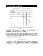
Страница 32: ...aph above If the internal circulator is adequate direct system piping can be utilized See section 4 page 12 for suggested direct supply return piping If the internal circulator is inadequate a seconda...

Страница 33: ...there is no excessive head loss on the external circulator that is installed In most circumstances 1 piping will be the best choice When the boiler is piped in this way the external circulator will no...

Страница 34: ...Plus Manual 34 14 1 Primary Secondary Piping All external piping components are to be supplied by the installer It is very important to use a hydraulic separator before secondary circulators 14 Piping...

Страница 35: ...al 35 14 2 Primary Secondary Piping with Zone Valves All external piping components are to be supplied by the installer It is very important to use a hydraulic separator before secondary circulators 1...

Страница 36: ...Riva Plus Manual 36 14 3 Manifold Piping with Zone Valves shown conn to radiators All external piping components are to be supplied by the installer 14 Piping Cont...

Страница 37: ...ss and remedy any leaks discovered Cold flush the system to remove any loose particles and any system debris before starting the boiler for the first time Reassemble the front panel of the case Return...

Страница 38: ...on the boiler Check the maximum gas pressure and compare the value on the gauge with the value indicated in the Section 2 on page 10 gas pressures at the burner Check the maximum gas flow at the gas m...

Страница 39: ...you obtain the required pressure by rotating clockwise the pressure increases Turn the boiler off and disconnect one of the two connectors E in Fig 15 5 Start the boiler and rotate the minimum gas pre...

Страница 40: ...Adjust the gas pressure at the injectors to the value indicated in the tables of section 2 By rotating the device clockwise the pressure increases After the adjustment operations bring the selector 3...

Страница 41: ...els supplied are placed on the boiler as shown in Figure 15 10 All the labels supplied with the boiler are numbered for reference According to Figure 15 10 place all the labels on the boiler Use label...

Страница 42: ...e proper use and adjustment of all system controls this will ensure the greatest possible safety and fuel economy Explain the function and use of the function switch Explain how to turn off the applia...

Страница 43: ...panel figure 16 2 D D D Figure 16 2 Set correctly the dip switch 2 to the correct position Fig 16 3 in accordance with the following table Gas supply Position of the switch 2 Natural gas On L P G Off...

Страница 44: ...anels Loosen the screws B Figure 17 2 Bring the bottom of the panels away from the boiler and lift them freeing them from the top hooks A A Figure 17 1 B B C C B B Figure 17 2 17 3 Emptying the Centra...

Страница 45: ...t necessary due to the fact that the ball bearings are sealed Check that the fan operates and that the visible impeller fins are free of any dirt or obstructions 17 8 Checking the flue Have the integr...

Страница 46: ...ri pressure indicated in the Section 2 on page 10 Venturi test points Figure 17 5 17 9 Visual inspection of appliance Visually inspect all water joints seals and connections for any evidence of leakag...

Страница 47: ...rate flue vent pipe E Separate vent sealing gaskets F Separate vent 90 degree elbows G Boiler vent adapter hardware H Separate flue intake pipe I Separate flue intake boiler adapter J Separate flue ex...

Страница 48: ...pipe B Coaxial termination pipe C Coaxial union clamp D Coaxial union gasket E Coaxial exhaust gasket F Coaxial boiler adapter gasket G Coaxial boiler adapter H Coaxial boiler adapter hardware I Coax...

Страница 49: ...collar hardware E Roof venting exhaust gasket F Roof venting exhaust adapter G Roof venting intake adapter H Roof venting intake gasket I Roof venting boiler adapter exhaust gasket J Roof venting boi...

Страница 50: ...Riva Plus Manual 50...

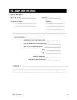
Страница 51: ...______________ Performance Tests GROSS STACK TEMPERATURE __________________ ROOM TEMPERATURE AMBIENT ________________ NET STACK TEMPERATURE _____________________ CO2 __________________ O2 ____________...

Страница 52: ...1796213550 17962 1355 0 4007 44A4 USA...

Отзывы: