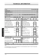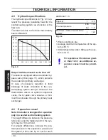
- 34 -
INST
ALLA
TION
INSTALLATION
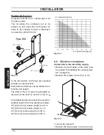
vertical plane.
Fig. 6.6
B
A
C
45°
90°
Type C
13
Vertical kit with 90° elbow (Fig. 6.6 B)
Co-axial 60/100 mm.
Supplied with a straight flanged adapter a
co-axial elbow and a co-axial pipe with ter
-
minal, this kit allows for a vertical rise of 0,5
m from the boiler. In all circumstances the
flue terminal must discharge horizontally
and the equivalent flue length must not ex
-
ceed 2,5 metres.
Elbows 45° & 90° (Fig. 6.6 C)
Coaxial 60/100 mm.
Elbow kits enable the standard flue kits to be
offset to overcome obstructions or ensure
the correct clearances for the flue terminal.
Each elbow used in addition to the standard
flanged elbow reduces the overall accept
-
able length of the flue systemas follows:
For the elbow of 45° loss
0,5 m
For the elbow of 90° loss
1 m
Twin pipe kits ø 80 mm (Fig. 6.7 - Fig. 6.8)
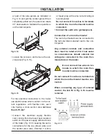
Fig. 6.7
Type C
12
Various twin (split) pipes kits and optional
accessories (elbows) are available to as
-
sist in the termination of the flue where the
boiler is installed in a location remote to an
outside wall.
These kits allow for separation of the air
supply pipe from the pipe that discharges
the exhaust gasses. Consequently it is pos
-
sible to extend the flue system to a greater
distance than that provided by the standard
horizontal co-axial flue.
If either an additional 45° or 90° accessory
elbow is used then the maximum permissi
-
ble length of either pipe must be reduced by
0.90 m or 1,65 m respectively.
N.B: The air intake and the flue outlet
must not terminate on opposite sides of
the building.
Содержание RIVA PLUS HE 24S ERP
Страница 55: ......

