


RCM
EDITION 09 / 2002
-
13
-
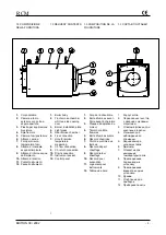
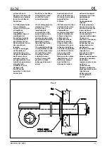
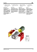
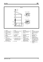
messa a terra della
caldaia al pannello
strumenti (4)
attraversando l’apposito
foro sul pannello (3)
5.
estrarre dal pannello
strumenti (4) i capillari
del termometro e dei
termostati e, attraverso
il foro del pannello
inserirli nell’apposito
pozzetto (5)
6.
fissare il pannello
strumenti al pannello
superiore (3) e montare
lo stesso sulla caldaia
7.
aprire il coperchio del
cruscotto porta
strumenti ed eseguire i
collegamenti elettrici
seguendo lo schema
ATTENZIONE!
-
Far passare i cavi
d’alimentazione del
pannello, della pompa
di circolazione e
dell’eventuale
collegamento del
termostato ambiente,
in idonei passacavi.
-
Per l’alimentazione del
bruciatore, utilizzare
cavo idoneo con
serracavo.
-
Collegare il filo della
messa a terra alla vite
contrassegnata con il
simbolo
-
Controllare
accuratamente il
fissaggio del
collegamento a terra, il
quale è obbligatorio e
deve corrispondere ai
parametri stabiliti dalle
norme CEI. La ditta
costruttrice non
risponde per danni a
persone o cose
derivanti dalla
mancata osservanza
di questa
fondamentale norma.
cable to instrument
panel (4) through the
hole in panel (3).
5.
unroll the capillary tubes
of the thermometer and
the thermostats out from
instrument panel (4) and
insert them in their
pocket (5) through the
hole in the panel.
6.
fasten the instrument
panel to top panel (3)
and install it on the
boiler.
7.
remove the instrument
control board cover and
make electrical
connections
ATTENTION!
-
Run the board,
circulation pump and
(if present) room
thermostat connection
supply cables through
the cable glands.
-
When bringing power
to the burner use the
cable gland.
-
Connect the ground
wire to the screw
marked with the
symbol
-
Carefully check the
ground connection.
This connection is
mandatory and must
comply standards EN
and local regulation
requirements. The
manufacturer will not
be responsible for
damage to persons or
property caused by
failure to comply with
this basic
requirement.
tableau de commande
(4) en traversant le trou
fait sur le panneaux (3).
5.
Dérouler délicatement
les capillaires des
sondes de température
et les engager dans le
doigt de gan.
6.
Fixer le tableau de bord
au tableau supérieur
et monter le même sur
la chaudière.
7.
Enlever le couvercle du
tableau de commandes
et exécuter les
branchements
électriques selon le
schéma
ATTENTION!
-
Faire passer les
câbles d’alimentation
du panneau, de la
pompe de circulation
et du branchement
éventuel du
thermostat d'ambiance
dans passes câbles.
-
Pour l’alimentation du
brûleur, utiliser câble
prévu pour ce service
-
Relier le fil de terre à
la vis repérée par le
symbole
-
Contrôler
soigneusement la
fixation de la
connexion de mise à
la terre, qui est
obligatoire et doit
correspondre aux
conditions visées par
les normes NF-C1500.
La firme constructrice
ne répond pas des
dommages causés
aux personnes ou aux
choses par suite de
l’inobservation de
cette norme
fondamentale.
заземление
к
приборной
панели
(4)
через
соответствующее
отверстие
на
панели
(3).
5.
Снять
с
приборной
панели
(4)
капилляры
термометра
и
термостатов
и
через
отверстие
на
панели
вставить
их
в
соответствующее
углубление
(5).
6.
Зафиксировать
приборную
панель
на
верхней
панели
(3)
и
установить
последнюю
на
котел
.
7.
Открыть
корпус
приборной
панели
и
провести
электрические
присоединения
согласно
схеме
.
ВНИМАНИЕ
-
Проводить
питание
панели
,
циркуляционного
насоса
и
возможного
соединения
с
термостатом
окр
.
среды
в
соответствующих
кабельных
проходах
.
-
Для
питания
горелки
использовать
соответствующий
кабель
с
кабельным
зажимом
.
-
Соединять
заземление
с
винтом
,
на
который
нанесен
символ
.
-
Аккуратно
проверить
фиксаж
заземления
,
который
обязателен
и
должен
соответствовать
параметрам
,
установленным
нормами
CEI.
Фирма
–
производитель
не
несет
ответственности
за
вред
,
причиненный
людям
или
имуществу
из
-
за
несоблюдения
этой
основной
нормы
.
Содержание RCM 105
Страница 2: ......


