8
GAS CONVERSION
36
8.1
Warnings
The commissioning of this boiler and sys-
tem must only be undertaken by a pro-
fessionally qualified person in accordance
with the requirements of the Gas Safety In-
stallation and Use Regulations and be ap-
proved by C.O.R.G.I.
Components used to adapt it to the type of gas
available must be genuine parts only.
8.2
Procedures
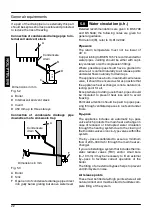
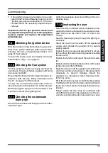
1 Check that the gas cock (14 in Fig. 8.1) fitted
under the boiler is turned off and the appliance
is switched off at the mains isolating spur.
Closed position
14
Fig. 8.1
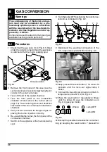
2 Remove the front panel of the case (see the
section
General access and emptying hydraulic
circuits
in the service manual).
3 Take off the lid of the sealed chamber.
4 Take the front panel of the combustion
chamber off and remove the burner (40 on
page 13). See section
Ignition and detection
electrodes
in the service manual for detailed in-
structions.
5 Carry out the conversion for the type of gas, re-
placing the burner injectors correctly.
6 Re---assemble the burner, the front panel of the
combustion chamber.
7 Switch on the appliance at the mains isolating
spur.
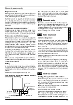
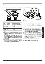
8 Turn the boiler OFF positioning the function se-
lector 8 as indicated in Fig. 8.2.
8
10
7
6
9
Fig. 8.2
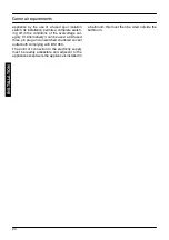
9 Disconnect the electrical connectors of the
C.h. temperature probe NTC 23 in Fig. 8.3
23
Fig. 8.3
10 Keep pressed the reset button 7 for about 10
seconds until the lock---out signal lamp 6
blinks.
11 Connect the the elctrical connectors of the C.h.
temperature probe NTC 23 in Fig. 8.3
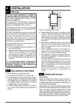
12 Press the reset button 7 repeatedly (4 times)
until the lamps 10 give the indication as in
Fig. 8.4 (gas type mode).
Where:
Lamp OFF
Lamp ON
Fig. 8.4
At this step it is possible to visualize the current set-
ting by keeping the reset button 7 pressed for
M
A
IN
TE
NA
NCE

