page 2
Installation and Operation Guide
TEC-X 1000
INSTALLATION
The TEC-X 1000 is designed to be installed into a standard 'gang' box outlet
and may be be daisy-chained with up to four additional TEC-X devices.
NOTE:
All Ethernet cabling should be connected prior to installation.
Mount the TEC-X 1000 to a junction back box outlet as follows:
The TEC-X 1000 comes 'partially' assembled with a pull tab installed over the
lower clip. This allows easier separation of the face and back plates to prevent
damage.
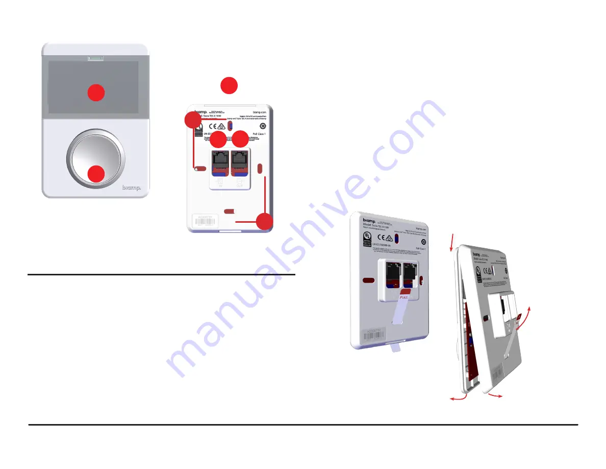
1. See Figure 2. Pull down and out on the face plate to separate it from the
back plate and remove the pull tab.
NOTE:
Do not snap the face plate onto the back plate until all finish work is done to the wall
surface and the Ethernet cables have been connected.
TEC-X 1000 Wall Control Panel
1. Capacitive-Touch LCD Display
2. Rotary Knob
3. LED Light Bar
4. Mounting Holes (4 Places)
5. Ethernet In (From Control Network)
6. Ethernet Out (Daisy Chain to TEC-X Devices)
1
2
4
4
5
6
3
Figure 2.
Separate face plate from back plate.
Figure 1.
Front and Back of
TEC-X 1000 Wall Control Panel


