17
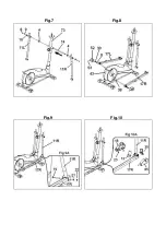
Next, position the left footrest (16L)
(marked with the letter “L”) on top of
the left foot (17L), refit the nuts (25),
the washers (24) and the screws (15)
removed previously and tighten
securely.
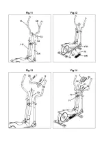
11. FITTING THE HANDLEBAR.-
Take the handlebar (78), remove
screws (8), position the ends of the
handlebar on the plate at the top of
the main post (73), Fig.13. Refit the
screws (8) removed previously.
12. FITTING MONITOR.-
ATTACHING THE FEEDBACK CABLE
Take hold of the cable (71), which is
sticking up out of the main post (73),
Fig.14, and plug it into the connector
(86) of the electronic unit (1), as
shown in Fig.14
FITTING THE HAND-GRIP CABLE.
Take hold of the Hand-grip connectors
(54), sticking out of the main post (73),
and plug them into the connectors (55)
located at the back of the monitor (1),
as shown in Fig.14.
ATTACHING THE MONITOR.-
Release screws (2), Fig.14, at the
back of the monitor.
Next, slide the front of the monitor
onto the plate on top of the main post
(73) in the direction of the arrow,
Fig.14, push the cables down into the
main post making sure not the pinch
any of the cables. Replace the screws
(2) removed previously.
ATTENTION:
It is important to retighten all of the
screws involved in assembling the
machine after approximately a week of
use as this will prevent any strange
noises and possible damage.
EXERTION SETTINGS.-
To provide an even level of exertion
during exercise, this appliance is
equipped with a tensioning control (77),
located on the main post (73), offering
various exertion settings, Fig.14.
To increase pedal resistance turn the
tensioning control (77) clockwise (+)
until the exertion level best suits your
exercise requirements.
To reduce pedal resistance turn the
tensioning control (77) anticlockwise (-).
LEVELLING.-
Once the unit has been placed into its
fi nal position, make sure that it sits fl
at on the fl oor and that it is level. This
can be achieved by screwing the
adjustable feet (44) up or down, as
shown in Fig.14.
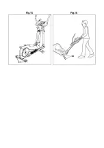
MOVEMENT & STORAGE.-
The unit is equipped with wheels (66)
to make it easier to move. The wheels
located at the front of your unit make it
easier to move it into a chosen
position, by lifting the rear of the unit
up slightly and pushing it, as shown in
Fig.15. Store your unit in a dry place,
preferably not subject to changes in
temperature.
Do not hesitate to get touch with the
Technical Assistance Service if you
have any queries by phoning customer
services (see last page in manual)
BH RESERVES THE RIGHT TO
MODIFY THE SPECIFICATIONS OF
ITS PRODUCTS WITHOUT PRIOR
NOTICE
Содержание Athlon G2334NVE
Страница 2: ...Fig 1 Fig 2 ...
Страница 3: ...Fig 3 Fig 4 Fig 5 Fig 6 ...
Страница 4: ...Fig 7 Fig 8 Fig 9 Fig 10 ...
Страница 5: ...Fig 11 Fig 12 Fig 13 Fig 14 ...
Страница 6: ...Fig 15 Fig 16 ...
Страница 48: ...48 G2334N ...


