background image


Transport, Installation and Connection 


4-13


4.8.3 

Laying the special cable KW6 for standard 
housing 


No contact chamber may remain bare ! 

All contact chambers in the contact insert have to be fitted 
with crimp contacts ! 

For this purpose use a suitable crimp tool (BFI part No. 
8980-4801-00) !


On the flame scanner side the external shielding is con-

nected to the housing mass by means of a clamp connec-
tion located between the plastic insert the threaded part in 
the cable gland. On the other side the outer shielding is 
cut off. The internal shielding is cut on both sides. 


No. 

Item 

Plastic insert 

Inner PUR jacket 

Crimp contact 

Contact insert 

Outer PUR jacket 

Union nut 

Thread 

Single core 

Outer shielding 

15 mm (0.59 inch) 

20 mm (0.78 inch) 

55 mm (2.16 inch) 

Содержание CFC 2000L

Страница 1: ...r OE Converter Type CFC 2000L Document No BA CFC2000L EN Rev10 Software settings see Document No HB CFC Com1 EN BFI Automation Mindermann GmbH Ruegenstrasse 7 D 42579 Heiligenhaus Germany Phone 49 2056 98946 0 Fax 49 2056 98946 42 http www bfi automation de ...

Страница 2: ......

Страница 3: ...lace Safety Ordinance BetrSichV 2 6 2 5 4 Safety test prior to initial operation 2 6 3 Technical data 3 1 3 1 General characteristic features 3 1 3 2 Electrical system Optical and Mechanical Data 3 2 3 3 Weight 3 4 3 4 Dimensions 3 4 3 5 Device Design block diagram CFC2000 3 5 4 Transport Installation and Connection 4 1 4 1 Scope of delivery 4 1 4 2 Accessories optional 4 1 4 3 Packaging 4 2 4 4 F...

Страница 4: ...ettings 5 2 5 3 1 The frequency filter 5 2 5 3 2 Safety switch OFF time of the safety channel 5 3 5 4 Factory settings 5 4 6 Operation of the Compact Flame Controller 6 1 6 1 Test of the Compact Flame Controller 6 1 7 Care and Maintenance 7 1 8 Failures 8 1 9 Order data 9 1 10 Accessories 10 1 ...

Страница 5: ...r and downtimes and increase the reliability and life of the device All illustrations and drawings in these operating instruc tions are shown for illustration purposes and are not au thoritative detailed designs The operating instructions always have to be accessible at the device They have to be read and applied by each person who is required to work with on the device This work may involve for e...

Страница 6: ...t in death or severe injury Follow the instructions that accompany this warning to prevent the potential risk of death and severe personal in jury This warning level indicates an potentially hazardous situ ation If the hazardous situation is not prevented this may result in slight or moderate injuries Follow the instructions that accompany this warning to prevent the injury of persons This warning...

Страница 7: ...closure and reproduction of documentation in whole or in part as well as the exploitation and communi cation of its content shall not be permitted unless ex pressly stated otherwise Offenders are liable for prosecu tion and the payment of damages We reserve all rights to exercise industrial property rights 1 4 Disposal information The flame detector is equipped with electrical and elec tronic comp...

Страница 8: ...d The recognised technical rules for safe and professional working also have to be observed in addition to the oper ating instructions and the regulations on accident preven tion applicable to the country and place of use The warranty shall become void for example in the event of inappropriate use use of impermissible equipment incorrect connection prior works that are not part of the supplied pro...

Страница 9: ...arly check that staff are safety conscious and aware of hazards and are observing the operating in structions Before starting work staff who are assigned to work with on the device have to have read and understood the operating instructions in particular the chapter on Safety as well as the relevant regulations The operating instructions and relevant regulations have to be stored in such a way tha...

Страница 10: ...ssories approved by us may be used This also applies to the components of other manufacturers that have been used The installation or use of non approved spare and acces sory parts and any unauthorized retrofits and modifica tions are not permitted for safety reasons and exclude any liability by BFI Automation for consequential damages BFI Automation is liable for possible errors or omissions with...

Страница 11: ...General aspects 1 7 1 8 Declaration of conformity ...

Страница 12: ...s 1 8 1 9 Address of the manufacturer BFI Automation Mindermann GmbH Ruegenstrasse 7 D 42579 Heiligenhaus Germany Tel 49 2056 98946 0 Fax 49 2056 98946 42 E mail info bfi automation de Internet www bfi automation de ...

Страница 13: ...ces The CFC 2000L may only be operated with fibre optic cables that were supplied by BFI Automation Danger when improperly used The device may cause hazards if it is not used as in tended and or for any other purposes The device has to be used only for the purposes for which it is intended The procedures described in the operating instructions have to be observed The manufacturer supplier shall no...

Страница 14: ...person Persons who are under the influence of drugs alcohol or medication that affects reactivity shall not be permitted to carry out work on the device Connection set up maintenance and repair work may only be carried out by qualified specialist staff This device may cause hazards if it is operated inappro priately by untrained staff or if it is not used for its in tended purpose Generally valid ...

Страница 15: ...eplace worn or defective parts Use suitable maintenance tools only After repair work refit all safety devices and carry out electrical and mechanical checks Check the operating instructions for details of displays as well as switch on and switch off procedures Prior to switching on the device make sure that no one can be endangered by the device The operating company is responsible for ensuring th...

Страница 16: ...as been fitted with warning and danger signs for the protection of operating staff These signs have to be observed Damaged or illegible signs have to be re placed immediately 2 4 2 Safety devices on the compact flame control ler The compact flame controller is equipped with the follow ing safety devices Housing protection against accidental contact Ex proof housing optional Device earthing explosi...

Страница 17: ...luding information on the replacement of parts assemblies have to be observed These tasks may only be carried out by authorised specialist staff Operating staff have to be informed before mainte nance or other special work is carried out A supervisor has to be appointed When working on the plug the cable must be discon nected from the power supply Screw connections which have been loosened during ...

Страница 18: ...nce BetrSichV In case of the coupling or installation of devices from vari ous manufacturers or suppliers the operating company has to carry out a precise test prior to start up in keeping with the German Workplace Safety Ordinance BetrSichV in force and the applicable electrical regulations In case of queries please get in touch with BFI Automa tion 2 5 4 Safety test prior to initial operation Da...

Страница 19: ...coal and mixed fuel burners Type IR2 IR For monitoring gas and oil fired burn ers in the IR range Type IR3 IR For flames of all kinds including resi dues H2S and special gases Two channel flame monitoring system Sensitivity adjustable separately for both channels by software Analog output flame intensity 0 4 to 20 mA Flame analysis possibility by software LED status display for flame relay and fla...

Страница 20: ...e with protection class III SELV Operating temperature 20 C to 70 C 4 F to 158 F Current output 0 4 to 20 mA Ra 250 Ohm Current window variable by software Fault output 24 V DC short circuit proof Range changeover External selection via 24 V DC signal Flame relay 1 changeover contact floating wire break detection optional max 48 V switching voltage max 1 A switching current fused with 0 5 A max 30...

Страница 21: ...s 122 x 120 x 80 mm 4 8 x 4 72 x 3 15 inch 232 x 232 x 166 5 mm 9 13 x 9 13 x 6 55 inch 276 x 276 x 218 mm 10 86 x 10 86 x 8 58 inch Type of protection Standard housing Ex housing IP 66 ATEX Zone 2 3G Ex ec nC IIC T4 Gc IP 66 ATEX Zone 1 Declaration of conformity of housing manufacturer Approvals CE IECEx ATEX CSA EAC Ex AGA CE0085BN0347 IECEx TUR 15 0029X TÜV 15 ATEX 7682 X 217345 RU C DE ГБ08 В ...

Страница 22: ...proof for 1 device for 2 or 3 devices approx 7 0 approx 13 0 approx 15 43 approx 28 66 3 4 Dimensions Standard 1 x Ex 2 or 3 x Ex mm inch mm inch mm inch Length 170 6 69 400 15 75 447 17 60 Width 122 4 80 226 8 90 276 10 87 Height with plug 95 3 74 165 6 49 218 8 58 ...

Страница 23: ...re amplifier 11 Data output RS232 3 Band pass filter 12 Flame relay 4 DC voltage part 13 Monitor relay 5 Frequency part 14 Relay contact with fuse F3 6 Modulation part J1 3 Monitor channel switch off time 7 Monitor channel J4 Frequency tap selection 8 Switchover to channel 2 external µP Microprocessor 9 Analog output 0 4 to 20 mA AND logic ...

Страница 24: ...Technical data 3 6 ...

Страница 25: ...C 2000L EN Harting cable terminal box kit not with ex proof hous ing 4 2 Accessories optional Power supply unit 230 115 V AC 1 ball flange with 2 flange disk 1 3 way ball valve 1 heating insulator 1 pressure barrier 5 bar Optical alignment device Ex proof housing Fiber optic cable Double nipple Software CFC Com1 Refer to the order papers for the exact scope of delivery and compare with the deliver...

Страница 26: ... in sufficient time before the expiry of any periods of preclusion and or limitation relating to the compensation claims against third parties 4 3 Packaging The compact flame controller is shipped in different pack aging materials The most frequently used packaging materials are card board and plastics foils foamed material Packaging has to be disposed of in an environmentally friendly way and in ...

Страница 27: ...nsport Installation and Connection 4 3 4 6 Space requirement See following illustration Standard housing Item SI unit mm US unit inch A G1 G1 B 155 6 1 C 152 5 98 D 120 4 72 E 122 4 8 F 106 4 17 G 88 3 46 ...

Страница 28: ...tion and Connection 4 4 Ex proof housing for 1 OE Converter For use in hazardous area Zone 1 Item SI unit mm US unit inch A 232 9 11 B 13 0 511 C 12 0 472 D 232 9 11 E 206 8 11 F 267 10 51 G 302 11 89 H 55 2 16 I 70 2 75 ...

Страница 29: ...er to ensure perfect flame monitoring the correct and low vibration position of the sighting tube relative to the flame is a significant pre requisite For selective burner monitoring the device has to be installed in such a way that the primary combustion zone in all load ranges is inside the visual angle of the compact flame controller The sighting axis must if possible intersect the first third ...

Страница 30: ...or inverted in horizontal and vertical direction The length and the diameter of the sighting tube have a direct influence on the analysable flame radiation as the visual angle of the lens system is defined Without re striction of the visual range the maximum length L of a sighting tube for conventional tube diameters D is as fol lows D 1 1 5 2 L SI m 0 5 0 8 1 1 L US ft 1 64 2 62 3 60 For this rea...

Страница 31: ...art No 1598 0141 00 must be employed At pressurised firing installations an additional 3 port shut off device optional Part No 1594 8831 00 should be in stalled for the sake of safety This prevents an escape of hot gases after the removal of the compact flame control ler and provides additional cooling and purging of the in stallation The entire mechanical peripheral system can be supplied by BFI ...

Страница 32: ... approved specialist staff Compact flame controllers with variable sensitivity set tings are set to the highest value at the manufacturer s works Compact flame controllers with variable frequency filters have a high signal sensitivity on account of the pre set low frequency harmonisation Compact flame controllers with a variable shutter are set at the manufacturer s works to Shutter open which ens...

Страница 33: ...d approved specialist staff All alignments and settings must be carried out when new spare parts have been fitted the compact flame con troller has been moved or the flame image has been changed e g due to additional fuels new burners changes in the burner air registers as well as during all initial installations For selective burner monitoring the device must be in stalled in such a way that the ...

Страница 34: ...sure that the available supply voltage complies with the voltage indicated on the type plate Prior to connection check the device and the connecting cables for visible damage For the contact assignment of the plug connector refer to the following terminal diagram The output signal 0 4 to 20 mA for the flame intensity is not separate from the supply voltage so that the signal re fers to the operati...

Страница 35: ...ame relay lead x 2 br Flame relay Flame ON x 3 pk Flame relay Flame OFF x 4 gn Power supply 24V DC 24V DC 200mA 5 ye Power supply GND GND 6 gr Analog output 0 4 to 20 mA 7 bl Switchover to channel 2 24V DC ext x 8 rd Fault output 24 V DC 100 mA x Connection of compact flame controller with internal heating optional Internal External Con tact Conduc tor colour Function Burner control mA display Pow...

Страница 36: ... colour BFI Special cable KW6 1 Flame relay Root white 2 Flame relay Flame ON brown 3 Flame relay Flame OFF pink 4 Power supply 24 V DC green 5 Power supply 0V GND yellow 6 Current output 0 4 20 mA gray 7 Sensitivity switchover channel 2 blue 8 Fault output 24V DC red ...

Страница 37: ... On the flame scanner side the external shielding is con nected to the housing mass by means of a clamp connec tion located between the plastic insert the threaded part in the cable gland On the other side the outer shielding is cut off The internal shielding is cut on both sides No Item 1 Plastic insert 2 Inner PUR jacket 3 Crimp contact 4 Contact insert 5 Outer PUR jacket 6 Union nut 7 Thread 8 ...

Страница 38: ...On the second stage the PUR sheath must be tightend with screwed cap II The inner screening shall be cut of on the scanner side and connected to ground at the flame controler No Item No Item 1 Screwed coupler 8 Screwed cap 2 2 Rubber casket 1 9 PUR cable sheath 3 Clamp collar 1 10 Ex de IIC housing 4 Outer braided shield 11 wire end ferrule 5 Clamp collar 2 12 heat shrinkable tubing 6 Screwed cap ...

Страница 39: ...age Store in a dry place Maximum relative humidity 60 Ensure that the packages are not stored outdoors In addition It has to be assured that the floor in the storage area will remain dry throughout the storage pe riod Protect from direct sunlight Storage temperature 15 C to 25 C 59 F to 77 F Store in a dust free location Avoid mechanical vibrations and damage ...

Страница 40: ...Transport Installation and Connection 4 16 ...

Страница 41: ...om neighbouring burners to be distinguished from the monitored flame Further function groups include i a the signal processing for the dynamic monitor channel that continuously moni tors the fault free state of the device A part of component defect results in the immediate switch off of the flame relay that represents a floating changeover contact for processing in the burner control ler The switc...

Страница 42: ...1 The frequency filter The CFC 2000 has a four step frequency filter in the sig nal input The evaluation of the flame signal by the soft ware takes place only downstream of the frequency filter Part of the extraneous light can therefore be filtered out before the evaluation by the software The limit frequen cies of the high pass filter can be set as follows Filter frequency Hz Switch 1 Switch 2 30...

Страница 43: ...3 bridged 5 seconds If a switch OFF time of 2 seconds is required the jumper must be inserted in position 2 3 seconds and the switch OFF time of the evaluation channel set by software to 2 seconds see Handbook HB CFC Com1 EN The shorter switch OFF time of the two channels always takes priority The safety switch OFF time during operation shut off time is also dependent on the software setting see H...

Страница 44: ... following hard and software settings are made by BFI Automation Current output 4 20mA Current Relay Function on Switch off time 1 s Frequency filter 60 Hz Switch off threshold 750 Switch on threshold 1200 Frequency evaluation off ...

Страница 45: ...e controller depends on the burner configuration as well as on the air flow and the spectral characteristic wave length 6 1 Test of the Compact Flame Controller In order to ensure correct operation the compact flame controller must be tested several times for all applications by starting and stopping the burner several times the flame relay must reliably shut down in all cases when there is no fla...

Страница 46: ...Operation of the Compact Flame Controller 6 2 ...

Страница 47: ...7 1 7 Care and Maintenance The compact flame controller is maintenance free For cleaning use a moist cloth to wipe the housing from the outside only and clean the lens in regular intervals Take care not to scratch the lens ...

Страница 48: ...Care and Maintenance 7 2 ...

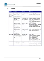
Страница 49: ...or self test fault Check fault memory Possibly remove plug for 5 seconds then start the burner again Replace compact flame controller Flame signal soft ware above the start ing thresholds Yellow LED ON Green LED ON Relay contact or wiring problem Check fuse F3 in relay output circuit Check electrical connection Burner fails Flame signal soft ware drops Below the shut off threshold the flame relay ...

Страница 50: ...Failures 8 2 ...

Страница 51: ...083 00 Compact flame controller in Ex proof housing GUB02 zone 1 Typ Part No OE Converter CFC 2000 UV LEX 7013 2034 00 OE Converter CFC 2000 UV1 LEX 7013 2004 00 OE Converter CFC 2000 IR LEX 7013 2044 00 OE Converter CFC 2000 IR2 LEX 7013 2064 00 OE Converter CFC 2000 IR3 LEX 7013 2084 00 2 compact flame controller in Ex proof housing GUB03 zone 1 Typ Part No OE Converter CFC 2000 UV LEX2 7013 203...

Страница 52: ...of housing GUB03 zone 1 Typ Part No OE Converter CFC 2000 UV LEX3 7013 2034 12 OE Converter CFC 2000 UV1 LEX3 7013 2004 12 OE Converter CFC 2000 IR LEX3 7013 2044 12 OE Converter CFC 2000 IR2 LEX3 7013 2064 12 OE Converter CFC 2000 IR3 LEX3 7013 2084 12 ...

Страница 53: ...10 5002 00 Special cable KW6 yard good 6060 0680 00 Swivel mount 1 with a 2 flange plate 6590 9020 01 3 Way ballvalve 1 1594 8831 00 Heating insulator 1 1598 0141 00 Double nipple 2 x 1 outer thread 1591 0241 00 Optical alignment device BFI 235 LWL 6030 0235 03 Scanner head SKL IR 6050 9010 00 Scanner head SKL UV 6050 9020 00 LWL for UV 60 200 C Stainless steel hose 5054 1xxx 10 LWL EX for UV 60 2...

Страница 54: ...L for X IR 60 200 C 5051 1xxx 00 LWL EX for X IR 60 200 C 5051 2xxx 00 Y LWL for X IR 60 200 C 5051 3xxx 00 LWL for X IR HT High tempera tur 60 300 C stainless steel hose 5052 1xxx 10 LWL EX for X IR HT High tem peratur 60 300 C stainless steel hose 5052 2xxx 10 xxx is the length of the fibre optic cable in decimeter More accessories you will find in our product catalog ...

Страница 55: ...Accessories 10 3 ...

Страница 56: ...Accessories 10 4 BFI Automation 2020 ...

Отзывы: