background image

ENGINE SPECIFICATIONS

2-4

Tensioning system

Automatic

Rocker arm/rocker arm shaft

Rocker arm inside diameter

9.985

10.000 mm (0.3931

0.3937 in)

Limit

10.015 mm (0.3943 in)

Rocker arm shaft outside diameter

9.966

9.976 mm (0.3924

0.3928 in)

Limit

9.941 mm (0.3914 in)

Rocker-arm-to-rocker-arm-shaft clearance

0.009

0.034 mm (0.0004

0.0013 in)

Limit

0.074 mm (0.0029 in)

Valve, valve seat, valve guide

Valve clearance (cold)

Intake

0.10

0.14 mm (0.0039

0.0055 in)

Exhaust

0.20

0.24 mm (0.0079

0.0094 in)

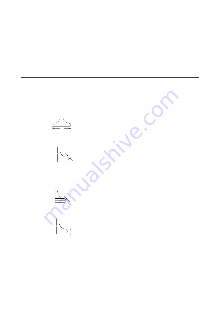
Valve dimensions

Valve head diameter A (intake)

19.40

19.60 mm (0.7638

0.7717 in)

Valve head diameter A (exhaust)

16.90

17.10 mm (0.6654

0.6732 in)

Valve face width B (intake)

1.538

2.138 mm (0.0606

0.0842 in)

Valve face width B (exhaust)

1.538

2.138 mm (0.0606

0.0842 in)

Valve seat width C (intake)

0.90

1.10 mm (0.0354

0.0433 in)

Limit

1.6 mm (0.06 in)

Valve seat width C (exhaust)

0.90

1.10 mm (0.0354

0.0433 in)

Limit

1.6 mm (0.06 in)

Valve margin thickness D (intake)

0.50

0.90 mm (0.0197

0.0354 in)

Valve margin thickness D (exhaust)

0.50

0.90 mm (0.0197

0.0354 in)

Valve stem diameter (intake)

4.475

4.490 mm (0.1762

0.1768 in)

Limit

4.445 mm (0.1750 in)

Valve stem diameter (exhaust)

4.460

4.475 mm (0.1756

0.1762 in)

Limit

4.430 mm (0.1744 in)

Valve guide inside diameter (intake)

4.500

4.512 mm (0.1772

0.1776 in)

Limit

4.550 mm (0.1791 in)

Valve guide inside diameter (exhaust)

4.500

4.512 mm (0.1772

0.1776 in)

Limit

4.550 mm (0.1791 in)

Valve-stem-to-valve-guide clearance (intake)

0.010

0.037 mm (0.0004

0.0015 in)

Limit

0.080 mm (0.0032 in)

A

B

C

D

Содержание RR 125 LC

Страница 1: ...e SAE 10W 30 SAE 10W 40 SAE 15W 40 SAE 20W 40 or SAE 20W 50 Recommended engine oil grade API service SG type or higher JASO standard MA Engine oil quantity Total amount 1 15 L 1 22 US qt 1 01 Imp qt Without oil filter element replacement 0 95 L 1 00 US qt 0 84 Imp qt With oil filter element replacement 1 00 L 1 06 US qt 0 88 Imp qt Oil filter Oil filter type Paper Oil pump Oil pump type Trochoid I...

Страница 2: ...8E Spark plug gap 0 7 0 8 mm 0 028 0 031 in Cylinder head Volume 9 90 10 50 cm 0 60 0 64 cu in Warpage limit 0 03 mm 0 0012 in Camshaft Drive system Chain drive left Camshaft lobe dimensions Intake A 30 225 30 325 mm 1 1900 1 1939 in Limit 30 125 mm 1 1860 in Intake B 25 127 25 227 mm 0 9893 0 9932 in Limit 25 027 mm 0 9853 in Exhaust A 30 232 30 332 mm 1 1902 1 1942 in Limit 30 132 mm 1 1863 in E...

Страница 3: ...B intake 1 538 2 138 mm 0 0606 0 0842 in Valve face width B exhaust 1 538 2 138 mm 0 0606 0 0842 in Valve seat width C intake 0 90 1 10 mm 0 0354 0 0433 in Limit 1 6 mm 0 06 in Valve seat width C exhaust 0 90 1 10 mm 0 0354 0 0433 in Limit 1 6 mm 0 06 in Valve margin thickness D intake 0 50 0 90 mm 0 0197 0 0354 in Valve margin thickness D exhaust 0 50 0 90 mm 0 0197 0 0354 in Valve stem diameter ...

Страница 4: ...kgf mm 134 41 lb in Spring rate K2 intake 36 58 N mm 3 73 kgf mm 208 87 lb in Spring rate K1 exhaust 23 54 N mm 2 40 kgf mm 134 41 lb in Spring rate K2 exhaust 36 58 N mm 3 73 kgf mm 208 87 lb in Installed compression spring force intake 140 00 162 00 N 14 28 16 52 kgf 31 47 36 42 lbf Installed compression spring force exhaust 140 00 162 00 N 14 28 16 52 kgf 31 47 36 42 lbf Spring tilt intake 2 5 ...

Страница 5: ...imensions B T 0 80 1 90 mm 0 03 0 07 in End gap installed 0 10 0 25 mm 0 0039 0 0098 in Limit 0 50 mm 0 0197 in Ring side clearance 0 030 0 065 mm 0 0012 0 0026 in Limit 0 100 mm 0 0039 in 2nd ring Ring type Taper Dimensions B T 0 80 2 10 mm 0 03 0 08 in End gap installed 0 10 0 25 mm 0 0039 0 0098 in Limit 0 60 mm 0 0236 in Ring side clearance 0 020 0 055 mm 0 0008 0 0022 in Limit 0 100 mm 0 0039...

Страница 6: ...late quantity 3 pcs Friction plate 2 thickness 2 90 3 10 mm 0 114 0 122 in Wear limit 2 80 mm 0 1102 in Plate quantity 1 pc Clutch plate thickness 1 45 1 75 mm 0 057 0 069 in Plate quantity 4 pcs Warpage limit 0 20 mm 0 0079 in Clutch spring free length 38 71 mm 1 52 in Minimum length 36 77 mm 1 45 in Spring quantity 4 pcs Long clutch push rod bending limit 0 500 mm 0 0197 in Transmission Transmis...

Страница 7: ... avoid warpage tight en multi fastener assemblies in a crisscross pat tern and progressive stages until the specified tightening torque is reached Unless otherwise specified tightening torque specifications re quire clean dry threads Components should be at room temperature A Distance between flats B Outside thread diameter A nut B bolt General tightening torques Nm m kgf ft lbf 10 mm 6 mm 6 0 6 4...

Страница 8: ...ator cover tightening sequence Clutch cover tightening sequence Crankcase tightening sequence 1 6 7 8 9 5 4 3 11 2 10 8 1 7 3 13 2 12 6 9 5 11 10 4 A 1 7 11 12 3 14 4 5 6 8 9 10 16 15 B 2 13 A Left crankcase B Right crankcase ...

Страница 9: ...LUBRICATION SYSTEM CHART AND DIAGRAMS EAS20390 LUBRICATION SYSTEM CHART AND DIAGRAMS EAS20400 ENGINE OIL LUBRICATION CHART 1 6 5 2 4 3 ...

Страница 10: ...LUBRICATION SYSTEM CHART AND DIAGRAMS EAS20410 LUBRICATION DIAGRAMS A 1 4 5 6 7 2 3 ...

Страница 11: ...LUBRICATION SYSTEM CHART AND DIAGRAMS 1 3 2 4 ...

Страница 12: ... Timing mark accessing screw 1 Crankshaft end accessing screw 2 5 Measure Valve clearance Out of specification Adjust a Turn the crankshaft counterclockwise b Align the TDC mark a on the generator rotor with the stationary pointer b on the genera tor cover c Check that the cam lobes are positioned as shown in the illustration d Measure the valve clearance with a thickness gauge 1 Out of specificat...

Страница 13: ...eps c and d a Set the main switch to ON b With the throttle wide open crank the engine until the reading on the compression gauge stabilizes c If the compression pressure is above the maximum specification check the cylinder head valve surfaces and piston crown for carbon deposits Carbon deposits Eliminate d If the compression pressure is below the min imum specification pour a teaspoonful of en g...

Страница 14: ...utch slippage Therefore do not add any chemical additives or use engine oils with a grade of CD c or higher and do not use oils labeled ENERGY CONSERVING II d Do not allow foreign materials to enter the crankcase 4 Start the engine warm it up for several min utes and then turn it off 5 Check the engine oil level again TIP Before checking the engine oil level wait a few minutes until the oil has se...

Страница 15: ...or to checking the ignition timing check the wiring connections of the entire ignition system Make sure all connections are tight and free of corrosion 1 Remove Timing mark accessing screw 1 2 Connect Timing light 1 Digital tachometer 3 Check Ignition timing a Start the engine warm it up for several min utes and then let it run at the specified en gine idling speed b Check that the stationary poin...

Страница 16: ... and then turn it off 11 Check Engine for engine oil leaks 12 Check Engine oil level 13 Check Engine oil pressure a Slightly loosen the oil check bolt 1 b Start the engine and keep it idling until engine oil starts to seep from the oil check bolt If no engine oil comes out after one minute turn the engine off so that it will not seize c Check the engine oil passages the oil filter element and the ...

Страница 17: ...ENGINE d Start the engine after solving the problem s and check the engine oil pressure again e Tighten the oil check bolt to specification T R Oil check bolt 7 Nm 0 7 m kgf 5 1 ft lbf ...

Страница 18: ...or Water pump 1 Spark plug cap 1 2 Spark plug 1 3 Crankshaft end accessing screw 1 4 Timing mark accessing screw 1 New New New New New New E E 4 12 11 14 15 16 15 13 6 7 1 2 4 4 10 9 8 5 4 3 5 E LS M LS 10 Nm 1 0 m kgf 7 2 ft Ibf T R 10 Nm 1 0 m kgf 7 2 ft Ibf T R 10 Nm 1 0 m kgf 7 2 ft Ibf T R 10 Nm 1 0 m kgf 7 2 ft Ibf T R 7 Nm 0 7 m kgf 5 1 ft Ibf T R 13 Nm 1 3 m kgf 9 4 ft Ibf T R 22 Nm 2 2 m ...

Страница 19: ...et 1 15 Dowel pin 2 16 Timing chain guide exhaust side 1 Removing the cylinder head Order Job Parts to remove Q ty Remarks New New New New New New E E 4 12 11 14 15 16 15 13 6 7 1 2 4 4 10 9 8 5 4 3 5 E LS M LS 10 Nm 1 0 m kgf 7 2 ft Ibf T R 10 Nm 1 0 m kgf 7 2 ft Ibf T R 10 Nm 1 0 m kgf 7 2 ft Ibf T R 10 Nm 1 0 m kgf 7 2 ft Ibf T R 7 Nm 0 7 m kgf 5 1 ft Ibf T R 13 Nm 1 3 m kgf 9 4 ft Ibf T R 22 N...

Страница 20: ...ch 2 loosen the camshaft sprocket bolt 3 Remove Camshaft sprocket TIP To prevent the timing chain from falling into the crankcase fasten it with a wire 1 4 Remove Cylinder head TIP Loosen the bolts in the proper sequence as shown Loosen each bolt 1 2 of a turn at a time After all of the bolts are fully loosened remove them Remove the cylinder head from the right side of the vehicle EAS24160 CHECKI...

Страница 21: ...the cylinder head several times EAS22B1004 CHECKING THE CAMSHAFT SPROCKET AND TIMING CHAIN GUIDE 1 Check Camshaft sprocket More than 1 4 tooth wear a Replace the camshaft sprocket timing chain and crank shaft as a set 2 Check Timing chain guide exhaust side Damage wear Replace EAS24200 CHECKING THE TIMING CHAIN TENSIONER 1 Check Timing chain tensioner Cracks damage rough movement Re place a Remove...

Страница 22: ...compression cam 2 projects from the camshaft exhaust cam as shown in the illustration A d Move the decompression lever 1 in the di rection of the arrow shown and check that the decompression cam does not project from the camshaft exhaust cam as shown in the illustration B EAS24230 INSTALLING THE CYLINDER HEAD 1 Install Cylinder head TIP Pass the timing chain through the timing chain cavity 2 Tight...

Страница 23: ...alve timing e While holding the camshaft temporarily tight en the camshaft sprocket bolt f Remove the wire from the timing chain 4 Install Timing chain tensioner gasket Timing chain tensioner a Remove the timing chain tensioner cap b While lightly pressing the timing chain ten sioner rod by hand turn it clockwise with a thin screwdriver 1 until it stops c Install the gasket and the timing chain te...

Страница 24: ...with the stationary pointer d on the cylinder head Out of alignment Correct Refer to the installation steps above 7 Tighten Camshaft sprocket bolt NOTICE ECA22B1010 Be sure to tighten the camshaft sprocket bolt to the specified torque to avoid the possibil ity of the bolt coming loose and damaging the engine 8 Measure 9 Valve clearance Out of specification Adjust T R Camshaft sprocket bolt 30 Nm 3...

Страница 25: ...ead 1 Locknut 4 2 Adjusting screw 4 3 Camshaft retainer 1 4 Rocker arm shaft 2 5 Intake rocker arm 1 6 Exhaust rocker arm 1 7 Camshaft 1 For installation reverse the removal proce dure M M M 1 1 2 2 4 4 7 3 1 1 2 2 5 E E E 6 M 7 Nm 0 7 m kgf 5 1 ft Ibf T R 7 Nm 0 7 m kgf 5 1 ft Ibf T R 7 Nm 0 7 m kgf 5 1 ft Ibf T R ...

Страница 26: ...excessive wear pit ting scratches Replace or check the lubri cation system 3 Measure Rocker arm inside diameter a Out of specification Replace 4 Measure Rocker arm shaft outside diameter a Out of specification Replace Camshaft lobe dimensions Intake A 30 225 30 325 mm 1 1900 1 1939 in Limit 30 125 mm 1 1860 in Intake B 25 127 25 227 mm 0 9893 0 9932 in Limit 25 027 mm 0 9853 in Exhaust A 30 232 30...

Страница 27: ...ctions a and hole b are positioned as shown in the illustra tion 4 Install Rocker arms Rocker arm shafts 1 TIP Make sure that the cutout a in each rocker arm shaft is facing downward as shown in the illustration Make sure the rocker arm shafts intake and exhaust are completely pushed into the cylin der head Rocker arm to rocker arm shaft clearance 0 009 0 034 mm 0 0004 0 0013 in Limit 0 074 mm 0 0...

Страница 28: ... Job Parts to remove Q ty Remarks Cylinder head Rocker arms Camshaft 1 Valve cotter 8 2 Upper spring seat 4 3 Valve spring 4 4 Intake valve 2 5 Exhaust valve 2 6 Valve stem seal 4 7 Lower spring seat 4 8 Valve guide 4 New New New New M M M M M M M 1 2 3 6 7 8 1 2 3 6 7 8 1 2 3 6 7 8 1 2 3 6 7 8 5 5 4 4 ...

Страница 29: ...leakage at the valve seat 1 2 Remove Valve cotters 1 TIP Remove the valve cotters by compressing the valve spring with the valve spring compressor and the valve spring compressor attachment 2 3 Remove Upper spring seat 1 Valve spring 2 Valve 3 Valve stem seal 4 Lower spring seat 5 TIP Identify the position of each part very carefully so that it can be reinstalled in its original place EAS24290 CHE...

Страница 30: ...installing the valve guide bore the valve guide with the valve guide reamer 3 to ob tain the proper valve stem to valve guide clearance TIP After replacing the valve guide reface the valve seat Valve stem to valve guide clear ance intake 0 010 0 037 mm 0 0004 0 0015 in Limit 0 080 mm 0 0032 in Valve stem to valve guide clear ance exhaust 0 025 0 052 mm 0 0010 0 0020 in Limit 0 100 mm 0 0039 in Val...

Страница 31: ...valve seats 1 Eliminate Carbon deposits from the valve face and valve seat 2 Check Valve seat Pitting wear Replace the cylinder head 3 Measure Valve seat width C a Out of specification Replace the cylinder head a Apply Mechanic s blueing dye Dykem b onto the valve face b Install the valve into the cylinder head c Press the valve through the valve guide and onto the valve seat to make a clear impre...

Страница 32: ...results lightly tap the valve seat while rotating the valve back and forth be tween your hands e Apply a fine lapping compound to the valve face and repeat the above steps f After every lapping procedure be sure to clean off all of the lapping compound from the valve face and valve seat g Apply Mechanic s blueing dye Dykem b to the valve face h Install the valve into the cylinder head i Press the ...

Страница 33: ...e recommended lubricant 3 Install Lower spring seat 1 Valve stem seal 2 Free length intake 41 71 mm 1 64 in Limit 39 62 mm 1 56 in Free length exhaust 41 71 mm 1 64 in Limit 39 62 mm 1 56 in Installed compression spring force intake 140 00 162 00 N 14 28 16 52 kgf 31 47 36 42 lbf Installed compression spring force exhaust 140 00 162 00 N 14 28 16 52 kgf 31 47 36 42 lbf Installed length intake 35 3...

Страница 34: ... installed in its original place Install the valve springs with the larger pitch a facing up 4 Install Valve cotters 1 5 To secure the valve cotters onto the valve stem lightly tap the valve tip with a soft face hammer NOTICE ECA13800 Hitting the valve tip with excessive force could damage the valve b Smaller pitch 2 1 ...

Страница 35: ... and piston Order Job Parts to remove Q ty Remarks Cylinder head 1 Cylinder 1 2 Cylinder gasket 1 3 Dowel pin 2 4 Piston pin clip 2 5 Piston pin 1 6 Piston 1 7 Top ring 1 8 2nd ring 1 9 Oil ring 1 E E E E New New New New 6 5 4 7 8 4 2 3 1 3 9 7 Nm 0 7 m kgf 5 1 ft Ibf T R ...

Страница 36: ... the piston pin puller set 4 2 Remove Top ring 2nd ring Oil ring TIP When removing a piston ring open the end gap with your fingers and lift the other side of the ring over the piston crown EAS24390 CHECKING THE CYLINDER AND PISTON 1 Check Piston wall Cylinder wall Vertical scratches Replace the cylinder and replace the piston and piston rings as a set 2 Measure Piston to cylinder clearance a Meas...

Страница 37: ...piston ring side clearance eliminate any carbon deposits from the piston ring grooves and piston rings 2 Install Piston ring into the cylinder TIP Level the piston ring into the cylinder with the piston crown C maximum of D1 D2 T maximum of D1 or D2 maximum of D5 or D6 R maximum of D1 D3 or D5 minimum of D2 D4 or D6 b 5 0 mm 0 20 in from the bottom edge of the piston Piston Diameter D 51 962 51 98...

Страница 38: ...t EAS24450 INSTALLING THE PISTON AND CYLINDER 1 Install Top ring 1 2nd ring 2 Oil ring expander 3 Lower oil ring rail 4 Upper oil ring rail 5 TIP Be sure to install the piston rings so that the manufacturer marks or numbers face up Piston ring Top ring End gap installed 0 10 0 25 mm 0 0039 0 0098 in Limit 0 50 mm 0 0197 in 2nd ring End gap installed 0 10 0 25 mm 0 0039 0 0098 in Limit 0 60 mm 0 02...

Страница 39: ...se 3 Lubricate Piston Piston rings Cylinder with the recommended lubricant 4 Offset Piston ring end gaps 5 Install Dowel pins Cylinder gasket Cylinder 1 TIP While compressing the piston rings with one hand install the cylinder with the other hand Pass the timing chain and timing chain guide intake side through the timing chain cavity Recommended lubricant Engine oil New 3 2 1 a New a Top ring b Up...

Страница 40: ... 3 Neutral switch lead connector 1 4 Generator cover 1 5 Generator cover gasket 1 6 Dowel pin 2 7 Crankshaft position sensor 1 8 Stator coil 1 9 Generator rotor 1 10 Woodruff key 1 11 Starter clutch gear 1 12 Bearing 1 3 E LS LS E LT LT E E E 18 9 12 13 3 New New 15 11 17 16 14 10 3 7 8 5 6 6 4 7 2 1 LT 10 Nm 1 0 m kgf 7 2 ft Ibf T R 10 Nm 1 0 m kgf 7 2 ft Ibf T R 10 Nm 1 0 m kgf 7 2 ft Ibf T R 14...

Страница 41: ...ter clutch assembly 1 Removing the generator and starter clutch Order Job Parts to remove Q ty Remarks 3 E LS LS E LT LT E E E 18 9 12 13 3 New New 15 11 17 16 14 10 3 7 8 5 6 6 4 7 2 1 LT 10 Nm 1 0 m kgf 7 2 ft Ibf T R 10 Nm 1 0 m kgf 7 2 ft Ibf T R 10 Nm 1 0 m kgf 7 2 ft Ibf T R 14 Nm 1 4 m kgf 10 ft Ibf T R 70 Nm 7 0 m kgf 50 ft Ibf T R ...

Страница 42: ...ouch the projections on the generator rotor 3 Remove Generator rotor 1 with the flywheel puller 2 Woodruff key NOTICE ECA13880 To protect the end of the crankshaft place an appropriate sized socket between the fly wheel puller set center bolt and the crank shaft TIP Make sure the flywheel puller is centered over the generator rotor EAS24560 REMOVING THE STARTER CLUTCH 1 Remove Starter clutch bolts...

Страница 43: ...t be replaced c When turning the starter clutch gear counter clockwise B it should turn freely otherwise the starter clutch is faulty and must be re placed EAS24600 INSTALLING THE STARTER CLUTCH 1 Install Starter clutch assembly Starter clutch bolts 1 TIP While holding the generator rotor 2 with the sheave holder 3 tighten the starter clutch bolts Do not allow the sheave holder to touch the projec...

Страница 44: ...ow the sheave holder to touch the projections on the generator rotor 3 Apply Sealant to the crankshaft position sensor stator as sembly lead grommet 4 Install Generator cover TIP Tighten the generator cover bolts in the proper tightening sequence as shown T R Generator cover bolt 10 Nm 1 0 m kgf 7 2 ft lbf 1 3 2 1 6 7 8 9 5 4 3 11 2 10 ...

Страница 45: ...ng the starter motor Order Job Parts to remove Q ty Remarks 1 O ring 1 2 Starter motor yoke 1 3 O ring 1 4 Armature assembly 1 5 Starter motor front cover brush holder set 1 6 Brush 2 7 Brush spring 2 New New LS 4 2 5 1 6 7 7 6 3 ...

Страница 46: ...ture assembly resistances commutator and insulation Out of specification Replace the starter motor a Measure the armature assembly resistances with the pocket tester b If any resistance is out of specification re place the starter motor 5 Measure Brush length a Out of specification Replace the starter motor front cover brush holder set 6 Measure Brush spring force Out of specification Replace the ...

Страница 47: ... Oil seal Damage wear Replace the starter motor front cover brush holder set EAS24800 ASSEMBLING THE STARTER MOTOR 1 Install Starter motor front cover brush holder set 1 Starter motor yoke 2 TIP Align the marks a on the starter motor yoke and starter motor front cover brush holder set 2 a 1 ...

Страница 48: ...l 1 Clutch cable 1 2 Oil filter element cover 1 3 Oil filter element 1 4 Clutch cover 1 5 Clutch cover gasket 1 6 Dowel pin 2 7 Oil seal 1 1 LS New 7 New New LS 4 6 6 5 2 6 4 3 10 Nm 1 0 m kgf 7 2 ft Ibf T R 10 Nm 1 0 m kgf 7 2 ft Ibf T R 10 Nm 1 0 m kgf 7 2 ft Ibf T R 7 Nm 0 7 m kgf 5 1 ft Ibf T R ...

Страница 49: ...late 1 1 8 Clutch plate 4 9 Friction plate 3 3 Green paint mark 10 Friction plate 2 1 11 Clutch damper spring 1 12 Clutch damper spring seat 1 13 Clutch boss nut 1 14 Lock washer 1 15 Clutch boss 1 16 Thrust washer 1 17 Clutch housing 1 New E E 10 4 4 8 9 9 8 8 9 8 7 E 6 4 5 3 2 1 11 12 13 14 15 16 17 18 8 Nm 0 8 m kgf 5 8 ft Ibf T R 12 Nm 1 2 m kgf 8 7 ft Ibf T R 70 Nm 7 0 m kgf 50 ft Ibf T R ...

Страница 50: ...n reverse the removal proce dure Removing the clutch Order Job Parts to remove Q ty Remarks New E E 10 4 4 8 9 9 8 8 9 8 7 E 6 4 5 3 2 1 11 12 13 14 15 16 17 18 8 Nm 0 8 m kgf 5 8 ft Ibf T R 12 Nm 1 2 m kgf 8 7 ft Ibf T R 70 Nm 7 0 m kgf 50 ft Ibf T R ...

Страница 51: ...CLUTCH Removing the push lever Order Job Parts to remove Q ty Remarks Exhaust pipe 1 Clutch push lever 1 2 Clutch push lever spring 1 3 Circlip 1 4 Oil seal 1 5 Bearing 1 New New LS E E 1 2 3 4 5 ...

Страница 52: ...ing procedure applies to all of the fric tion plates 1 Check Friction plate Damage wear Replace the friction plates as a set 2 Measure Friction plate thickness Out of specification Replace the friction plates as a set TIP Measure the friction plate at four places 3 1 2 Friction plate 1 thickness 2 90 3 10 mm 0 114 0 122 in Wear limit 2 80 mm 0 110 in Friction plate 2 thickness 2 90 3 10 mm 0 114 0...

Страница 53: ...gth a Out of specification Replace the clutch springs as a set EAS25150 CHECKING THE CLUTCH HOUSING 1 Check Clutch housing dogs 1 Damage pitting wear Deburr the clutch housing dogs or replace the clutch housing TIP Pitting on the clutch housing dogs will cause er ratic clutch operation 2 Check Bearing Damage wear Replace the bearing and clutch housing EAS25160 CHECKING THE CLUTCH BOSS 1 Check Clut...

Страница 54: ... to BALANCER GEARS on page 5 53 EAS25210 CHECKING THE PRIMARY DRIVEN GEAR 1 Check Primary driven gear 1 Damage wear Replace the primary drive gear and clutch housing as a set Excessive noise during operation Replace the primary drive gear and clutch housing as a set EAS25240 INSTALLING THE CLUTCH 1 Install Conical spring washer 1 TIP Install the conical spring washer as shown in the illustration 2...

Страница 55: ...all a friction plate and then alternate between a clutch plate and a friction plate 8 Install Pressure plate Clutch springs Clutch spring bolts 1 TIP Tighten the clutch spring bolts in stages and in a crisscross pattern 9 Adjust Clutch mechanism free play a Check that the projection a on the clutch push lever 1 aligns with the mark b shown on the crankcase in the illustration by pushing the clutch...

Страница 56: ...ocknut to specification 10 Install Oil seal 1 11 Install Clutch cover TIP Tighten the clutch cover bolts in the proper tight ening sequence as shown 12 Adjust Clutch cable free play Refer to ADJUSTING THE CLUTCH CABLE FREE PLAY on page 3 12 T R Short clutch push rod locknut 8 Nm 0 8 m kgf 5 8 ft lbf Installed depth a 1 4 1 9 mm 0 055 0 075 in T R Clutch cover bolt 10 Nm 1 0 m kgf 7 2 ft lbf 2 3 3 ...

Страница 57: ...oving the oil pump Order Job Parts to remove Q ty Remarks Clutch housing Balancer drive gear 1 Oil baffle plate 1 2 Oil pump assembly 1 3 Oil pump drive gear 1 LT LT 2 3 1 10 Nm 1 0 m kgf 7 2 ft Ibf T R 4 Nm 0 4 m kgf 2 9 ft Ibf T R ...

Страница 58: ...isassembling the oil pump Order Job Parts to remove Q ty Remarks 1 Oil pump housing cover 1 2 Pin 1 3 Oil pump driven gear 1 4 Oil pump inner rotor 1 5 Oil pump outer rotor 1 6 Oil pump housing 1 1 5 2 4 6 3 E E ...

Страница 59: ...G THE OIL PUMP 1 Lubricate Oil pump inner rotor Oil pump outer rotor Oil pump driven gear with the recommended lubricant 2 Install Oil pump outer rotor Oil pump inner rotor 1 Oil pump driven gear Pin 2 TIP When installing the inner rotor align the pin 2 in the oil pump shaft with the groove a in the in ner rotor 1 Inner rotor 2 Outer rotor 3 Oil pump housing Inner rotor to outer rotor tip clearanc...

Страница 60: ... to CHECKING THE OIL PUMP on page 5 49 EAS25020 INSTALLING THE OIL PUMP 1 Install Oil pump assembly NOTICE ECA22B1011 After tightening the screws make sure the oil pump turns smoothly T R Oil pump assembly screw 4 Nm 0 4 m kgf 2 9 ft lbf 2 a 1 ...

Страница 61: ...d stopper lever Order Job Parts to remove Q ty Remarks Clutch housing Shift pedal 1 Pin 1 2 Shift shaft 1 3 Circlip 1 4 Shift shaft spring 1 5 Stopper lever 1 6 Stopper lever spring 1 7 Oil seal 1 LT 5 1 3 6 7 4 2 New New New E LS 10 Nm 1 0 m kgf 7 2 ft Ibf T R ...

Страница 62: ...S25450 INSTALLING THE SHIFT SHAFT 1 Install Oil seal 1 to the left crankcase 2 2 Install Stopper lever 1 Stopper lever spring 2 TIP Install the stopper lever spring as shown in the illustration Hook the ends of the stopper lever spring onto the stopper lever and the crankcase boss 3 Mesh the stopper lever with the shift drum seg ment assembly 3 Install Shift shaft 1 TIP Hook the end of the shift s...

Страница 63: ...ve Q ty Remarks Clutch housing 1 Primary drive gear nut 1 2 Balancer driven gear nut 1 3 Washer 1 4 Primary drive gear 1 5 Balancer drive gear 1 6 Straight key 1 7 Lock washer 1 8 Balancer driven gear 1 9 Straight key 1 10 Spacer 1 1 3 4 5 6 9 7 8 2 10 New 60 Nm 6 0 m kgf 43 ft Ibf T R 50 Nm 5 0 m kgf 36 ft Ibf T R ...

Страница 64: ...ary drive gear Refer to CHECKING THE PRIMARY DRIVE GEAR on page 5 44 EAS22B1011 INSTALLING THE PRIMARY DRIVE GEAR AND BALANCER GEARS 1 Install Balancer driven gear 1 Lock washer Balancer drive gear 2 Primary drive gear Washer 3 Balancer driven gear nut Primary drive gear nut TIP Align the punch mark a in the balancer drive gear 2 with the punch mark b in the balancer driven gear 1 Be sure to insta...

Страница 65: ...ARS Place an aluminum plate b between the bal ancer drive gear 3 and the balancer driven gear 4 and then tighten the primary drive gear nut 3 Bend the lock washer tab along a flat side of the nut a 4 1 3 3 1 2 b 4 ...

Страница 66: ...arter motor Balancer gears Generator rotor 1 Timing chain guide intake side 1 2 Timing chain guard 1 3 Timing chain 1 4 Engine oil drain plug 1 8 9 8 New New New New 1 3 2 4 5 6 7 11 11 10 12 LS 10 Nm 1 0 m kgf 7 2 ft Ibf T R 10 Nm 1 0 m kgf 7 2 ft Ibf T R 10 Nm 1 0 m kgf 7 2 ft Ibf T R 10 Nm 1 0 m kgf 7 2 ft Ibf T R 20 Nm 2 0 m kgf 14 ft Ibf T R 32 Nm 3 2 m kgf 23 ft Ibf T R ...

Страница 67: ... 2 12 Left crankcase 1 Separating the crankcase Order Job Parts to remove Q ty Remarks 8 9 8 New New New New 1 3 2 4 5 6 7 11 11 10 12 LS 10 Nm 1 0 m kgf 7 2 ft Ibf T R 10 Nm 1 0 m kgf 7 2 ft Ibf T R 10 Nm 1 0 m kgf 7 2 ft Ibf T R 10 Nm 1 0 m kgf 7 2 ft Ibf T R 20 Nm 2 0 m kgf 14 ft Ibf T R 32 Nm 3 2 m kgf 23 ft Ibf T R ...

Страница 68: ...Removing the oil seal and bearings Order Job Parts to remove Q ty Remarks Crankshaft Balancer Transmission 1 Oil seal 1 2 Bearing retainer 1 3 Bearing 7 LT E E E 2 1 3 3 3 3 3 3 3 LS 7 Nm 0 7 m kgf 5 1 ft Ibf T R ...

Страница 69: ...ake sure the crankcase halves sepa rate evenly EAS25580 CHECKING THE CRANKCASE 1 Thoroughly wash the crankcase halves in a mild solvent 2 Thoroughly clean all the gasket surfaces and crankcase mating surfaces 3 Check Crankcase Cracks damage Replace Oil delivery passages Obstruction Blow out with compressed air EAS22B1013 CHECKING THE TIMING CHAIN AND TIMING CHAIN GUIDE 1 Check Timing chain Damage ...

Страница 70: ...aces TIP Do not allow any sealant to come into contact with the oil gallery 3 Install Right crankcase onto the left crankcase TIP Turn the shift drum segment 1 to the position shown in the illustration In this position the shift drum segment teeth will not contact the crankcase during crankcase installation Tap lightly on the right crankcase with a soft face hammer 4 Install Crankcase bolts TIP Ti...

Страница 71: ...CRANKCASE A Left crankcase B Right crankcase A 1 7 11 12 3 14 2 13 4 5 6 8 9 10 16 15 B ...

Страница 72: ...CRANKSHAFT EAS25960 CRANKSHAFT Removing the crankshaft and balancer Order Job Parts to remove Q ty Remarks Crankcase 1 Balancer 1 2 Crankshaft 1 New New 1 2 LS LS E E ...

Страница 73: ...n Replace the crank shaft bearing or both TIP Turn the crankshaft slowly 2 Measure Big end side clearance Out of specification Replace the crank shaft 3 Measure Crankshaft width Out of specification Replace the crank shaft 4 Check Crankshaft sprocket Damage wear Replace the crankshaft Bearing Cracks damage wear Replace the crank shaft 5 Check Crankshaft journal Scratches wear Replace the crankshaf...

Страница 74: ...e the oil seal lips with lithium soap based grease and each bearing with engine oil TIP Hold the connecting rod at top dead center TDC with one hand while turning the nut of the crankshaft installer bolt with the other Turn the crankshaft installer bolt until the crankshaft bot toms against the bearing 1 2 4 5 3 ...

Страница 75: ...ly and shift forks Order Job Parts to remove Q ty Remarks Crankcase 1 Shift fork guide bar 1 2 Spring 2 3 Shift drum assembly 1 4 Shift fork R 1 5 Shift fork C 1 6 Shift fork L 1 7 Drive axle assembly 1 8 Main axle assembly 1 9 Long clutch push rod 1 E 7 8 9 2 1 2 3 4 5 6 E E E E ...

Страница 76: ...ing the main axle Order Job Parts to remove Q ty Remarks 1 2nd pinion gear 1 2 6th pinion gear 1 3 3rd 4th pinion gear 1 4 Circlip 1 5 Toothed washer 1 6 5th pinion gear 1 7 Main axle 1st pinion gear 1 E E E 2 1 4 5 3 6 7 New ...

Страница 77: ... gear 1 3 6th wheel gear 1 4 Washer 1 5 1st wheel gear 1 6 Spacer 1 7 5th wheel gear 1 8 Circlip 1 9 Toothed washer 1 10 4th wheel gear 1 11 3rd wheel gear 1 12 Drive axle 1 2 1 9 10 7 5 6 11 8 4 12 3 New 2 1 9 10 7 5 6 11 8 4 12 3 New 2 1 9 10 7 5 6 11 8 4 12 3 New 2 1 9 10 7 5 6 11 8 4 12 3 New E E E E ...

Страница 78: ...ce the shift forks and shift fork guide bar as a set EAS26270 CHECKING THE SHIFT DRUM ASSEMBLY 1 Check Shift drum groove Damage scratches wear Replace the shift drum assembly Shift drum segment 1 Damage wear Replace the shift drum as sembly Shift drum bearing 2 Damage pitting Replace the shift drum as sembly EAS26290 CHECKING THE TRANSMISSION 1 Measure Main axle runout with a centering device and ...

Страница 79: ... push rod bending limit Out of specification Replace the long clutch push rod EAS29020 ASSEMBLING THE MAIN AXLE AND DRIVE AXLE 1 Install Toothed washer 1 Circlip 2 TIP Be sure to install the circlip so that its sharp edge a is facing away from the toothed wash er and gear Be sure the circlip ends b are positioned at the axle spline groove c 2 Install 2nd pinion gear 1 TIP Press the 2nd pinion gear...

Страница 80: ...ight side of the engine and be in the following sequence R C L 2 Check Transmission Rough movement Repair TIP Apply engine oil to each gear and bearing thor oughly Before assembling the crankcase make sure that the transmission is in neutral and that the gears turn freely 1 2 3 5 4 ...

Страница 81: ...Parts to remove Q ty Remarks Coolant Fuel tank cover assembly 1 Coolant temperature sensor coupler 1 2 Coolant temperature sensor 1 3 Thermostat cover 1 4 Thermostat 1 5 Radiator inlet hose 1 1 3 4 5 2 New 10 Nm 1 0 m kgf 7 2 ft Ibf T R 18 Nm 1 8 m kgf 13 ft Ibf T R ...

Страница 82: ...ator inlet hose Cracks damage Replace EAS26480 INSTALLING THE THERMOSTAT 1 Install Thermostat TIP Install the thermostat with its breather hole a facing up 2 Install Copper washer Coolant temperature sensor NOTICE ECA22B1012 Use extreme care when handling the coolant temperature sensor Replace any part that was dropped or subjected to a strong im pact 3 Fill 4 Cooling system with the specified amo...

Страница 83: ...water pump Order Job Parts to remove Q ty Remarks Coolant Fuel tank cover assembly 1 Radiator outlet hose 1 2 Water pump breather hose 1 3 Cylinder head breather hose 1 4 Water pump assembly 1 1 3 2 4 LS LS New New 10 Nm 1 0 m kgf 7 2 ft Ibf T R ...

Страница 84: ...cover 1 2 Water pump housing cover gasket 1 3 Impeller shaft retainer 1 4 Impeller shaft 1 5 Water pump housing plate 1 6 Water pump housing gasket 1 7 Water pump seal 1 8 Bearing 1 9 Water pump housing 1 LT New New New LS 1 2 9 7 4 8 3 5 6 10 Nm 1 0 m kgf 7 2 ft Ibf T R 10 Nm 1 0 m kgf 7 2 ft Ibf T R ...

Страница 85: ...Cracks damage wear Replace Bearing Rough movement Replace Radiator outlet hose Cracks damage Replace EAS26560 ASSEMBLING THE WATER PUMP 1 Install Water pump seal 1 into the water pump housing 2 NOTICE ECA14080 Never lubricate the water pump seal surface with oil or grease 2 Lubricate Water pump seal lip 3 Install Water pump housing gasket 1 Water pump housing plate 2 Impeller shaft 2 1 2 1 New A P...

Страница 86: ...S26580 INSTALLING THE WATER PUMP 1 Install Water pump assembly 1 O rings 2 TIP Align the projection a on the impeller shaft with the slit b on the camshaft sprocket bolt Lubricate the O rings with a thin coat of lithium soap based grease 2 Fill 3 Cooling system with the specified amount of the recom mended coolant 3 Check Cooling system Leaks Repair or replace all faulty parts 4 Measure 5 Radiator...

Страница 87: ...revents the starter motor from operating when neither of these condi tions has been met In this instance the starting circuit cut off relay is open so current cannot reach the starter motor When at least one of the above conditions has been met the starting circuit cut off relay is closed and the engine can be started by pressing the start switch 1 2 3 12 6 5 4 13 a b 7 8 10 11 9 a WHEN THE TRANSM...

Страница 88: ... probe 4 Negative tester probe Result Continuity between 3 and 4 1 Positive battery terminal 2 Negative battery terminal 3 Positive tester probe 4 Negative tester probe Result Continuity between 3 and 4 1 Positive battery terminal R R W R B L B 2 1 4 3 1 3 2 4 R B L B R W L W R Y L B R Y W B 1 2 3 4 2 Negative battery terminal 3 Positive tester probe 4 Negative tester probe Result Continuity betwe...

Страница 89: ...ess b Connect the pocket tester Ω 1 to the diode terminals as shown c Check the diode for continuity d Check the diode for no continuity EAS28060 CHECKING THE SPARK PLUG CAP 1 Check Spark plug cap resistance Out of specification Replace Turn signal relay output voltage DC 12 V Positive tester probe brown white 1 Negative tester probe ground Br W Br 1 Br W Br 1 No continuity Positive tester probe b...

Страница 90: ...sistance 2 Check Secondary coil resistance Out of specification Replace a Disconnect the spark plug cap from the igni tion coil b Connect the pocket tester Ω 1k to the ig nition coil as shown c Measure the secondary coil resistance EAS28930 CHECKING THE IGNITION SPARK GAP 1 Check Ignition spark gap Out of specification Perform the ignition system troubleshooting starting with step 5 Resistance 5 0...

Страница 91: ...sconnect the spark plug cap from the spark plug b Connect the ignition checker 1 as shown c Set the main switch to ON and the engine stop switch to d Measure the ignition spark gap a e Crank the engine by pushing the start switch and gradually increase the spark gap un til a misfire occurs Minimum ignition spark gap 6 0 mm 0 24 in ...

Страница 92: ... in the vicinity b Check the starter motor operation EAS28150 CHECKING THE STATOR COIL 1 Disconnect Stator coil coupler from the wire harness 2 Check Stator coil resistance Out of specification Replace the crank shaft position sensor stator assembly a Connect the pocket tester Ω 1 to the stator coil coupler as shown b Measure the stator coil resistance EAS28170 CHECKING THE RECTIFIER REGULATOR 1 C...

Страница 93: ... Connect the pocket tester DC 20 V to the rectifier regulator coupler as shown c Start the engine and let it run at approximate ly 5000 r min d Measure the charging voltage Charging voltage 14 V at 5000 r min Positive tester probe red 1 Negative tester probe ground W R W W 1 ...

Отзывы: