background image

- 42 -

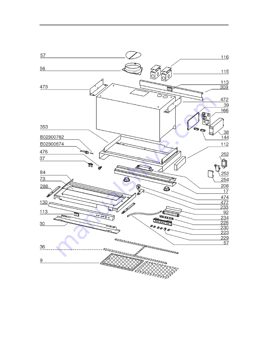
PIEZAS DE REPUESTO

MODELO U102E

Содержание Range Hood U102E

Страница 1: ...Model U102E ENGLISH 2 FRANÇAIS 16 ESPAÑOL 30 BEST BY BROAN P O Box 140 Hartford WI 53027 REGISTER YOUR PRODUCT ONLINE AT www bestbybroan com register 99043487B ...

Страница 2: ...lways be vented to the outdoors 7 Do not use this unit with any separate solid state speed control device 8 To reduce the risk of fire use only metal ductwork 9 This unit must be grounded TO REDUCE THE RISK OF A RANGE TOP GREASE FIRE A Never leave surface units unattended at high settings Boilovers cause smoking and greasy spillovers that may ignite Heat oils slowly on low or medium settings B Alw...

Страница 3: ... off and restart have the hood serviced 7 For best capture of cooking impurities the bottom of the hood should be a minimum of 22 1 2 above the cooking surface 8 Three installers are recommended because of the large size and weight of this hood 9 This product is equipped with a thermostat which may start blower automatically To reduce the risk of injury and to prevent power from being switched on ...

Страница 4: ...been activated After 30 hours of operation the center segment of the display blinks and remains lit indicating that filters need to be cleaned The Time Delay switch activates a delay off feature When pushed the blower will continue to operate at the current speed setting for 10 minutes before automatically turning itself off The Filter Alarm Reset switch is used to reset the 30 hour filter timer A...

Страница 5: ...eater than 4 Amps may damage the transformer 5 Reinstall the fuse cap and grease filter 6 Reconnect power at the service entrance HALOGEN BULBS This range hood requires two halogen bulbs Type T3 12Volt 20Watt Max G 4 Base WARNING Always switch off the electricity supply before carrying out any operations on the appliance To change bulbs 1 Open the cover by prying from the proper slots DO NOT ROTAT...

Страница 6: ...all that is usually needed 2 Follow all cleaning by rinsing with clear water Wipe dry with a clean soft cloth to avoid water marks 3 For discolorations or deposits that persist use a non scratching household cleanser or stainless steel polishing powder with a little water and a soft cloth 4 For stubborn cases use a plastic scouring pad or soft bristle brush together with cleanser and water Rub lig...

Страница 7: ... Brackets 4 Machine Screws M4 x 30mm Pan Head 7 Mounting Screws 3 9 x 9 5mm Pan Head 4 Flat Washers 4 mm diameter 8 Screws 4 2 x 15mm Pan Head 1 Installation Instructions 8 DAMPER DUCT CONNECTOR 4 FLAT WASHERS 2 MOUNTING BRACKETS DECORATIVE SPACER 4 MACHINE SCREWS M4 x 30mm PAN HEAD 8 MOUNTING SCREWS 4 2 x 15mm PAN HEAD 7 MOUNTING SCREWS 3 9 x 9 5mm PAN HEAD GLASS VISOR ...

Страница 8: ...2 18 36 40 1 2 21 42 PREPARE THE HOOD 1 Loosley assemble both mounting brackets to the hood using M4 x 30mm machine screws and flat washers 2 Place the 8 damper duct connector on top of the range hood discharge opening Remove tape from damper flaps Secure with 4 3 9 x 9 5mm screws 3 Assemble wall spacer to the hood with 3 3 9 x 9 5mm screws NOTE The spacer is designed to fill a 5 8 gap between the...

Страница 9: ... the front of the wall cabinet Center the hood on the wall cabinet 3 Tighten the 4 mounting bracket machine screws previously installed 4 Fasten the hood to the cabinet with 8 4 2 x 15mm pan head screws Make sure that screws will not penetrate finished cabinet side walls 5 Open the slide out drawer Place the glass panel into the open recessed area of the drawer 6 Slide glass left or right until it...

Страница 10: ...l joints between ductwork sections 5 An 8 round to 10 round transition Model 414 is required For best air performance install the transition as close to the range hood as possible HOOD 22 1 2 ABOVE COOKING SURFACE EXTERIOR BLOWER 8 TO 10 ROUND TRANSITION 8 ROUND DUCT EXTERIOR BLOWER 10 ROUND DUCT 8 ROUND ELBOW 10 ROUND DUCT EXTERIOR OR IN LINE BLOWER SELECTION CAUTION Either an exterior blower or ...

Страница 11: ... 11 IN LINE BLOWER ...

Страница 12: ... pinched between the cover and box Exterior or In line blower connection 1 Make electrical connections at the exterior or in line blower see instructions provided with the exterior or in line blower Power connection at hood 1 Run 120 VAC electrical power cable to the hood wiring box marked 120VAC input 2 Remove the cover from the wiring box and remove one knockout 3 Securetheconduittothewiringboxt...

Страница 13: ...itation may not apply to you BROAN S OBLIGATION TO REPAIR OR REPLACE AT BROAN S OPTION SHALL BE THE PURCHASER S SOLE AND EXCLUSIVE REMEDY UNDER THIS WARRANTY BROAN SHALL NOT BE LIABLE FOR INCIDENTAL CONSEQUEN TIAL OR SPECIAL DAMAGES ARISING OUT OF OR IN CONNECTION WITH PRODUCT USE OR PERFORMANCE Some states do not allow the exclusion or limitation of incidental or consequential damages so the abov...

Страница 14: ... 14 SERVICE PARTS MODEL U102E ...

Страница 15: ...Panel 36 model 130 B003101220 Front Panel 30 model 130 B003101227 Front Panel 42 model 144 B03292287 Wire Clamp 166 B08086701 Wiring Board 208 B02300783 Transformer 223 B03294171 Switch botton 233 B03294740 Closing 252 B03292349 Microswitch box 253 B02300620 Microswitch 254 B03292350 Microswitch box cover 288 B020111650 Runner ball 309 B003101216 Spacer 36 model 309 B003101222 Spacer 30 model 309 ...

Страница 16: ...lisez pas cet appareil avec un appareil contrôlant la vitesse à état solide 8 Afindediminuertoutrisqued incendien utilisezquedesconduitsenmétal 9 Votre appareil doit être relié à la terre ATTENTION POUR REDUIRE LES RISQUES D INCENDIE DES MATIERES GRASSES QUI SONT EN TRAIN DE CUIRE A Ne laissez jamais ni vos éléments chauffants ni vos casseroles ou poêles sur le feu sans les contrôler si vous régle...

Страница 17: ...tie électrique 6 Le moteur de votre hotte a un thermostat qui éteindra automatiquement le moteur s il est surchauffé Le moteur se remettra en marche lorsqu il se sera refroidi Si le moteur continue à s éteindre et à se remettre en marche faites vérifier votre hotte 7 Pour mieux capturer les impuretés de cuisine le bas de votre hotte devrait être à une distance minimum de 22 1 2 57 1 cm au dessus d...

Страница 18: ...inutes est activée Après 30 heures d utilisation le segment central de l indicateur clignote puis demeure allumé indiquant que les filtres doivent être nettoyés L Interrupteur de minuterie actionne un dispositif de minuterie qui se trouvait désactivé Lorsque l on appui sur ce bouton le ventilateur continue à fonctionner pendant 10 minutes au régime réglé puis s arrête automatiquement Le bouton de ...

Страница 19: ...t endommager le transformateur 5 Replacez le capuchon du porte fusible et le filtre à graisse 6 Rétablissez le courant au panneau électrique AMPOULES HALOGENES Cette hotte requiert deux ampoules halogènes Type T3 12Volt 20Watt Max G 4 Base AVERTISSEMENT Coupez toujours l alimentation électrique avant d effectuer tous travaux sur l appareil Pour remplacer les ampoules 1 Ouvrez le couvercle en faisa...

Страница 20: ...s ou les dépôts tenaces utilisez un nettoyant domestique non abrasif ou une poudre à polir l acier inoxydable avec un peu d eau et un chiffon doux 4 Pour la saleté rebelle utilisez un tampon à récurer en plastique ou une brosse à poils doux avec un nettoyant et de l eau Frottez doucement dans le sens des lignes de polissage ou du grain de l acier Évitez de trop appuyer au risque de gâcher la surfa...

Страница 21: ...e montage 4 Vis mécanique M4 x 30 mm à tête cylindrique 7 Vis de montage 3 9 x 9 5 mm à tête cylindrique 4 Rondelles de 4 mm de diamètre 8 Vis 4 2 x 15 mm à tête cylindrique 1 Directives d installation CLAPET RACCORD DE CONDUIT DE 20 3 CM 8 PO 4 RONDELLES 2 BRIDES DE MONTAGE CALE DÉCORATIVE 4 VIS MÉCANIQUES M4 X 30 MM À TÊTE CYLINDRIQUE 8 VIS MÉCANIQUES 4 2 X 15 MM À TÊTE CYLINDRIQUE 7 VIS DE MONT...

Страница 22: ...0 1 2 po 21 po 42 po VIS DE MONTAGE 3 9x9 5mm CALE VIS DE MONTAGE 3 9x9 5mm VIS MÉCANIQUES M4x30mm RONDELLE PRÉPARATION DE LA HOTTE 1 Assemblez les brides de montage sur la hotte sans les serrer à l aide des vis mécaniques M4 x 30 mm et des rondelles 2 Placez le clapet raccord de conduit de 20 3 cm 8 po sur l ouverture de sortie du dessus de la hotte Enlevez le ruban qui retient les volets du clap...

Страница 23: ...nt de l armoire Centrez la hotte sur l armoire 3 Serrez les quatre 4 vis mécaniques des brides préalablement installées 4 Fixez la hotte à l armoire avec huit 8 vis de 4 2 x 15 mm à tête cylindrique Assurez vous que les vis ne pénètrent pas le fini des parois de l armoire 5 Ouvrez la visière coulissante Placez le panneau de verre dans l ouverture encastrée 6 Glissez la vitre à gauche ou à droite j...

Страница 24: ...d efficacité installez l adapteur aussi proche que possible de la hotte CHOIX DE VENTILATEUR EXTERNE OU IN LINE ATTENTION avec cette hotte on peut utiliser soit un ventilateur externe soit In Line La hotte U102E doit être installée avec un ventilateur des modèles suivants EB6 EB9 EB12 EB15 ILB3 ILB6 ILB9 ou ILB11 uniquement On ne peut pas utiliser d autres ventilateurs les ventilateurs sont vendus...

Страница 25: ... 25 VENTILATEUR IN LINE ...

Страница 26: ...bles n est coincé entre le couvercle et le boîtier Connexion du ventilateur extérieur ou in Line 1 Effectuez les branchements électriques du ventilateur extérieur ou In Line voir les instructions fournies avec le ventilateur Connexion de l alimentation de la hotte 1 Acheminez un câble électrique de 120 VCA au boîtier de câblage de la hotte portant l inscription 120VAC input entrée de 120 VCA 2 Enl...

Страница 27: ...ués par Broan NuTone LLC une mauvaise installation ou une installation contraire aux instructions recommandées La durée de toute garantie tacite est limitée à la période d un an stipulée pour la garantie expresse Certains territoires ou provinces interdisent les restrictions relatives à la durée d une garantie implicite La restriction susmentionnée peut donc ne pas s appliquer dans votre cas L OBL...

Страница 28: ... 28 PIECES DE RECHANGE MODÈLE U102E ...

Страница 29: ...e 130 B003101208 Panneau avant modèle 91 5 cm 36 po 130 B003101220 Panneau avant modèle 76 2 cm 30 po 130 B003101227 Panneau avant modèle 106 7 cm 42 po 144 B03292287 Attache de câble 166 B08086701 Circuit de câblage 208 B02300783 Transformateur 223 B03294171 Bouton d interrupteur 233 B03294740 Fermoir 252 B03292349 Boîte de mini interrupteur 253 B02300620 Mini interrupteur 254 B03292350 Couvercle...

Страница 30: ...idad a estado sólido 8 Para evitar el riesgo de incendio use solamente conductos de metal 9 Esta unidad tiene que ser conectada a tierra PARA EVITAR EL RIESGO DE FUEGO POR ALTO NIVEL DE GRASA A Nunca abandone los quemadores con el fuego alto La cocción causa humo y restos de grasa que pueden arder Caliente el aceite a fuego medio o bajo B Encienda siempre la campana cuando cocine a fuego alto o cu...

Страница 31: ... Para limpiar mejor las impurezas al cocinar la distancia entre la parte inferior de la campana y la zona de cocción debe ser mínimo 22 1 2 pulg 57 1 cm 8 Debido a su gran tamaño y peso se recomienda su montaje por parte de 3 técnicos esperializados 9 Este producto está dotado de un termostato que pone en marcha automáticamente el motor Para reducir el riesgo de daños y evitar que se encienda acci...

Страница 32: ...gado demorado de 10 minutos Después de 30 horas de funcionamiento el segmento central de la pantalla destellará y permanecerá encendido esto indica que es necesario limpiar los filtros El interruptor de retardo temporal activa la función de apagado demorado Al apretarlo el ventilador continuará funcionando a la velocidad presente durante 10 minutos antes de apagarse automáticamente El interruptor ...

Страница 33: ...sformador 5 Vuelva a colocar la tapa del portafusibles y el filtro de grasa 6 Vuelva a conectar la energía en la entrada de servicio BOMBILLAS DE HALÓGENO Esta campana de estufa requiere dos bombillas de halógeno tipo T3 12Volt 20Watt Max G 4 Base ADVERTENCIA Siempre apague el suministro eléctrico antes de realizar cualquier operación en el electrodoméstico Para cambiar las bombillas 1 Haga palanc...

Страница 34: ... las descoloraciones o los depósitos use un limpiador casero que no deje arañazos o un polvo de pulir para acero inoxidable con un poco de agua y un trapo suave 4 En los casos más persistentes use una esponja desengrasadora o un cepillo de cerdas suaves junto con el limpiador y agua Frote ligeramente en la misma dirección de las líneas de pulido o grano del acabado de acero inoxidable No aplique d...

Страница 35: ...na M4 x 30 mm cabeza troncocónica 7 tornillos 3 9 x 9 5 mm cabeza troncocónica 4 arandelas planas 4 mm de diámetro 8 tornillos 4 2 x 15 mm cabeza troncocónica 1 folleto de instrucciones de instalación CONECTADOR DEL REGULADOR DE TIRO CONDUCTO DE 8 PULG 4 ARANDELAS PLANAS 2 SOPORTES DE MONTAJE SEPARADOR ORNAMENTAL 4 TORNILLOS DE MÁQUINA M4 x 30 mm CABEZA TRONCOCÓNICA 8 TORNILLOS 4 2 x 15 mm CABEZA ...

Страница 36: ...MONTAJE 3 9x9 5mm SEPARADOR DE PARED TORNILLOS DE MONTAJE 3 9x9 5mm TORNILLOS DE MÁQUINA M4x30mm ARANDELA PREPARACIÓN DE LA CAMPANA 1 Instale sin apretar ambos soportes de montaje en la campana mediante los tornillos de máquina M4 x 30 mm y las arandelas planas 2 Coloque el conectador del regulador de tiro conducto de 8 pulg por encima de la abertura de descarga de la campana Quite la cinta de las...

Страница 37: ...l gabinete de la pared Centre la campana en el gabinete de la pared 3 Apriete los 4 tornillos de máquina en los soportes de montaje instalados previamente 4 Asegure la campana al gabinete con 8 tornillos de cabeza troncocónica de 4 2 x 15 mm Tenga cuidado de que los tornillos no penetren las paredes laterales del gabinete terminado 5 Abra el cajón deslizante Coloque el panel de vidrio en el área e...

Страница 38: ...mitirá que la campana funcione más eficientemente 3 Los tramos largos de conductos codos y transiciones reducirán el rendimiento de la campana Use tan pocos de ellos como sea posible Es posible que se requieran conductos más grandes de para un mejor funcionamiento con tramos largos de conductos 4 Una vez instalado el ventilador exterior conecte el conducto metálico redondo y trabaje hacia atrás ha...

Страница 39: ... 39 VENTILADOR IN LINE ...

Страница 40: ...en atrapados entre la cubierta y la caja Conexión del ventilador exterior o In Line 1 Haga las conexiones eléctricas en el ventilador exterior o In Line consulte las instrucciones adjuntas a éste Conexión de energía eléctrica en la campana 1 Tienda el cableado de la casa de 120 VCA a la caja de cableado de la campana marcada 120VAC input entrada de 120 VCA 2 Quite la tapa de la caja de cableado 3 ...

Страница 41: ...ado negligencia accidente mantenimiento o reparación inadecuada no hecha por Broan NuTone LLC instalación incorrecta o instalación en contra de las instrucciones de instalación recomendadas La duración de cualquier garantía implícita se limita al período de un año como se especifica para la garantía explícita Algunos estados no permiten la limitación de la duración de una garantía implícita de man...

Страница 42: ... 42 PIEZAS DE REPUESTO MODELO U102E ...

Страница 43: ...ntalla modelo de 30 pulg 84 BE3403762 Visor de pantalla modelo de 42 pulg 112 B03294746 Protección del cableado 113 B02011284 Etiqueta 115 BE3334250 Caja de conexiones 116 BE3334252 Cubierta de la caja de conexiones 130 B003101208 Panel frontal modelo de 36 pulg 130 B003101220 Panel frontal modelo de 30 pulg 130 B003101227 Panel frontal modelo de 42 pulg 144 B03292287 Abrazadera de cables 166 B080...

Страница 44: ...04307336 1N ...

Отзывы: