background image

- 7 -

INSTALL SUPPORT SYSTEM

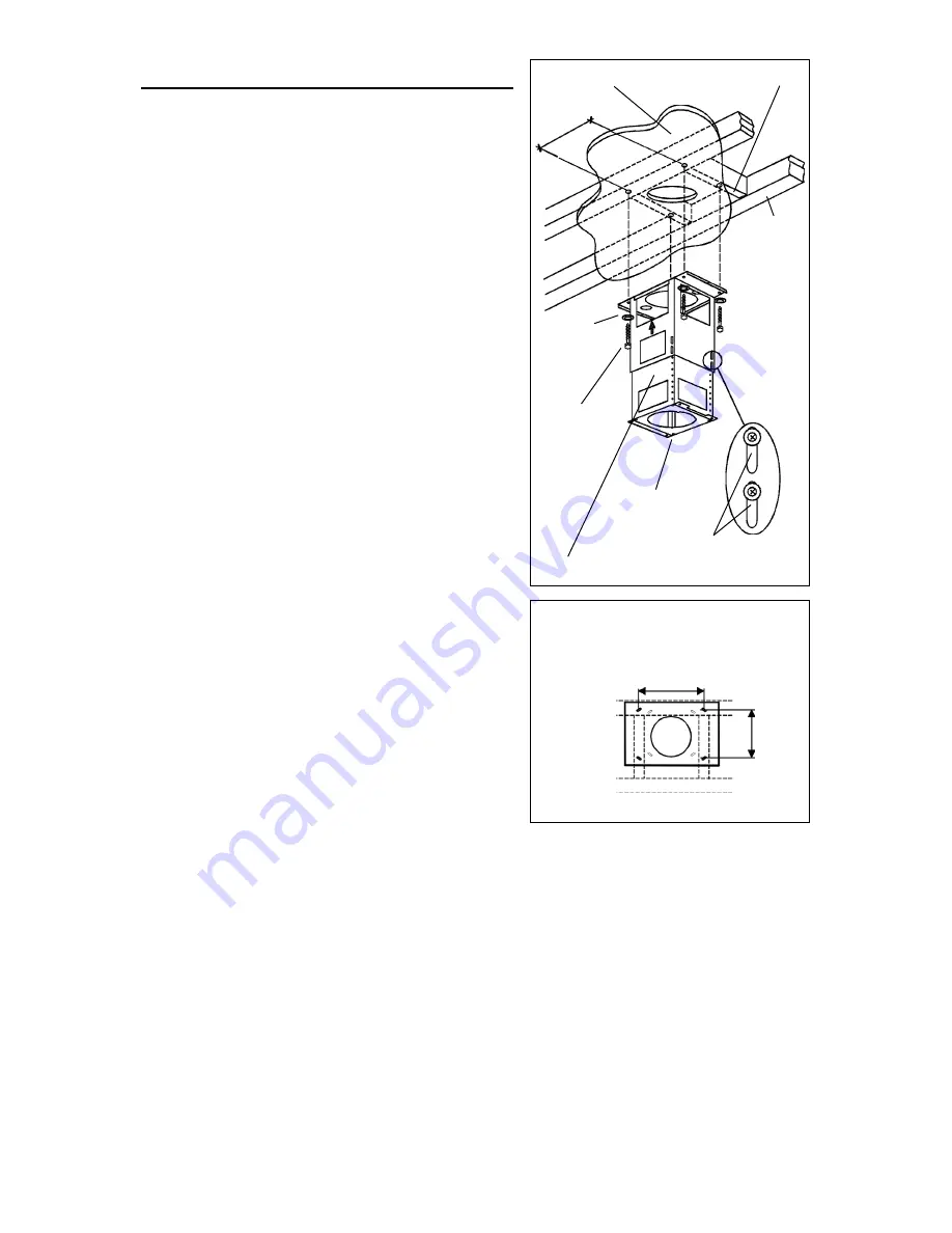
1. At hood location, install 2 X 4 

cross framing

between 

ceiling joists

 using dimensions

shown.

2. Finish the ceiling surface. Be sure to mark

the location of the ceiling joists and cross

framing.

3. Position 

the support frame 

as shown. The

UP ARROW should point towards the ceiling

after installation.

4. Secure the upper half of support frame to

joists and cross framing with four screws

(6x70mm and four washers (D.6.4mm).

Make sure screws are driven into center of

joists and framing for maximum strength.

5. Adjust the overall height of the support frame.

Loosen and re-tighten the 4 screws in the

height adjustment slots

 as necessary.

Insert 4 screws (3.9x9.5mm) and 4 washers

(D.4.5mm) located in the Hardware

Package.

Note that the hood height is 10” and that the

bottom of the hood must be 24” min. and 30”

max. above the cooktop.

CEILING

JOISTS

CROSS FRAMING

FRONT

HEIGHT

ADJUSTMENT

SLOTS

SUPPORT

FRAME

9

13

/

16

DRYWALL

MOUNTING

SCREWS

(6x70mm)

WASHERS

(Ø6.4mm)

TOP VIEW OF

SUPPORT FRAME

9

13

/

16

7

13

/

16

Содержание IEX42

Страница 1: ...IS 15 ESPAÑOL 28 Model IEX42 In USA BEST Hartford Wisconsin In CANADA BEST Drummondville QC Canada REGISTER YOUR PRODUCT ONLINE AT www BestRangeHoods com register For additional Information visit www BestRangeHoods com ...

Страница 2: ...s be vented to the outdoors 7 Do not use this unit with any separate solid state speed control device 8 To reduce the risk of fire use only metal ductwork 9 This unit must be grounded TO REDUCE THE RISK OF A RANGE TOP GREASE FIRE A Never leave surface units unattended at high settings Boilovers cause smoking and greasy spillovers that may ignite Heat oils slowly on low or medium settings B Always ...

Страница 3: ...If the motor continues to shut off and restart have the hood serviced 8 For best capture of cooking impurities the bottom of the hood should be a minimum of 24 and a maximum of 30 above the cooking surface 9 Two installers are recommended because of the large size and weight of this hood 10 This product is equipped with a thermostat which may start blower automatically To reduce the risk of injury...

Страница 4: ... 1 Parts Bag B080810004 containing 4 Mounting Screws 6 x 70mm 8 Washers Ø 6 4mm 4 Washers Ø 4 5mm 13 Mounting Screws 3 9 x 9 5mm Pan Head 4 Nuts 1 Installation Instructions 1 Warranty Card SUPPORT FRAME DECORATIVE FLUE 13 MOUNTING SCREWS 3 9x9 5mm Pan Head 8 WASHERS Ø6 4mm 4 WASHERS Ø4 5mm DUCT COLLAR 4 NUTS 4 MOUNTING SCREWS 6x70mm ...

Страница 5: ...ation where the Exterior or In Line Blower will be mounted See illustrations below for mounting location suggestions and restrictions 2 A straight short duct run will allow the hood to perform most efficiently 3 Long duct runs elbows and transitions will reduce the performance of the hood Use as few of them as possible Larger ducting may be required for best performance with long duct runs 4 After...

Страница 6: ... 6 IN LINE BLOWER ...

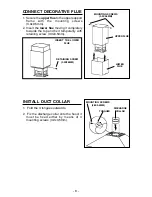
Страница 7: ...crews 6x70mm and four washers D 6 4mm Make sure screws are driven into center of joists and framing for maximum strength 5 Adjust the overall height of the support frame Loosen and re tighten the 4 screws in the height adjustment slots as necessary Insert 4 screws 3 9x9 5mm and 4 washers D 4 5mm located in the Hardware Package Note that the hood height is 10 and that the bottom of the hood must be...

Страница 8: ...RGE COLLAR TONGUES CONNECT DECORATIVE FLUE 1 Secure the upper flue to the upper support frame with the mounting screws 3 9x9 5mm 2 Insert the lower flue moving it completely towards the top and fix it temporarily with retaining screw 3 9x9 5mm LOWER FLUE UPPER FLUE MOUNTING SCREWS 3 9X9 5MM INSERT THE LOWER FLUE RETAINING SCREW 3 9X9 5MM MOUNTING SCREWS 3 9X9 5MM ...

Страница 9: ...ectrical box 2 Mount hood to support frame 3 Insert four 4 bolts through the top of the hood from the inside 4 Use four 4 nuts and four 4 washers Ø6 4mm to secure hood to support frame as shown 5 Replace electrical box BOLT NUT USE 4 NUTS AND 4 WASHERS WASHER D 6 4MM ELECTRICAL BOX ...

Страница 10: ...wiring box and remove one knockout 3 Secure the conduit to the wiring box through a conduit connector 4 Make electrical connections at the hood Connect white to white red to black and green to ground 5 Replace the wiring box cover and screws Make sure wires are not pinched between the cover and box Exterior or In line blower connection 1 Make electrical connections at the exterior or in line blowe...

Страница 11: ... screws from the lower flue and set it in place on the hood 4 Secure decorative flue to hood with two mounting screws 3 9x9 5mm LOWER FLUE 8 ROUND METAL DUCT RETAINING SCREWS MOUNTING SCREWS 3 9X9 5MM BOTTOM TRIM REPLACEMENT 1 Remove the four 4 screws from the inside of the hood 2 Remove the trim by pulling downward 3 Slide the new trim upward onto hood 4 Replace the four screws removed in step 1 ...

Страница 12: ...t use a non scratching household cleanser or stainless steel polishing powder with a little water and a soft cloth O For stubborn cases use a plastic scouring pad or soft bristle brush together with cleaser and water Rub lightly in direction of polishing lines or grain of the stainless finish Avoid using too much pressure which may mar the surface O DO NOT allow deposits to remain for long periods...

Страница 13: ...ses excessive heat above the cooking surface 1 If blower is OFF it turns blower ON to HIGH speed 2 If blower is ON at a lower speed setting it turns blower up to HIGH speed When the temperature level drops to normal the blower will return to its original setting WARNING The HEAT SENTRY thermostat can start the blower even if the hood is turned OFF When this occurs it is impossible to turn the blow...

Страница 14: ...installation contrary to recom mended installation instructions The duration of any implied warranty is limited to the one year period as specified for the express warranty Some states do not allow limitation on how long an implied warranty lasts so the above limitation may not apply to you BROAN NUTONE S OBLIGATION TO REPAIR OR REPLACE AT BROAN NUTONE S OPTION SHALL BE THE PURCHASER S SOLE AND EX...

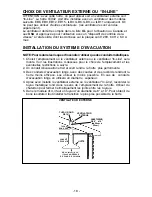
Страница 15: ...ez pas cet appareil avec un appareil contrôlant la vitesse à état solide 8 Afindediminuertoutrisqued incendien utilisezquedesconduitsenmétal 9 Votre appareil doit être relié à la terre ATTENTION POUR REDUIRE LES RISQUES D INCENDIE DES MATIERES GRASSES QUI SONT EN TRAIN DE CUIRE A Ne laissez jamais ni vos éléments chauffants ni vos casseroles ou poêles sur le feu sans les contrôler si vous réglez l...

Страница 16: ... en contact avec la partie électrique 7 Le moteur de votre hotte a un thermostat qui éteindra automatiquement le moteur s il est surchauffé Le moteur se remettra en marche lorsqu il se sera refroidi Si le moteur continue à s éteindre et à se remettre en marche faites vérifier votre hotte 8 Pour mieux capturer les impuretés de cuisine le bas de votre hotte devrait être à une distance minimum de 24 ...

Страница 17: ...uation 1 Sachet B080810004 avec 4 Vis d assemblage 6 x 70mm 8 Rondelles Ø 6 4mm 4 Rondelles Ø 4 5mm 13 Vis d assemblage 3 9 x 9 5mm Tête ronde 4 Ecrous 1 Instructions pour l installation 1 Garantie 13 VIS D ASSEMBLAGE 3 9x9 5mm Tête ronde 8 RONDELLES Ø6 4mm 4 RONDELLES Ø4 5mm COLLIER D EVACUA TION 4 NUTS 4 VIS D ASSEMBLAGE 6x70mm STRUCTURE DE SUPPORT CONDUIT DECORATIF ...

Страница 18: ...Line sera monté Voir les illustrations ci dessous pour le choix de l emplacement et les éventuelles restrictions à suivre 2 Un conduit d évacuation étroit et court rendra la hotte plus performante 3 Des conduits d évacuation longs avec des coudes et des raccords rendront la hotte moins efficace Les utiliser le moins possible En cas de conduits d évacuation longs on utilisera un diamètre supérieur ...

Страница 19: ... 19 VENTILATEUR IN LINE ...

Страница 20: ... D 6 4mm Assurez vous que les vis soient bien centrées dans les solives et dans le cadre croisé de sorte que le tout soit bien solide 5 Réglez la hauteur totale de la structure de support Désserrez et resserrez les 4 vis dans les fissures permettant de régler la hauteur selon ce qui est nécessaire Installez 4 vis 3 9x9 5mm et 4 rondelles D 4 5mm qui se trouvent à l intérieur du sachet accessoires ...

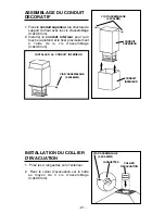
Страница 21: ...ixer provisoirement à l aide de la vis d assemblage 3 9x9 5mm CONDUIT SUPERIEUR CONDUIT INFERIEUR INSTALLER LE CONDUIT INFERIEUR VIS D ASSEMBLAGE 3 9X9 5MM INSTALLATION DU COLLIER D EVACUATION 1 Pliez les 4 languettes vers l extérieur 2 Fixez le collier d évacuation sur la hotte au moyen de 4 vis d assemblage 3 9x9 5mm LANGUETTES COLLIER D EVACUATION VIS D ASSEMBLAGE 3 9X9 5MM VIS D ASSEMBLAGE 3 9...

Страница 22: ...age de votre hotte a la structura de support 3 Insérez quatre 4 boulons par le haut de votre hotte de l intérieur 4 Fixez votre hotte à la structure de support comme cela est indiqué au moyen des quatre 4 écrous et quatre 4 rondelles Ø6 4mm 5 Remettez a boîte de connexion electrique ECROU BOULON UTILISEZ 4 ECROUS ET 4 RONDELLES RONDELLES BOÎTE DE CONNEXION ELECTRIQUE ...

Страница 23: ...er un knockout 3 Fixer le conduit au boîtier de connexion à l aide d un connecteur approprié pour ce conduit 4 Faire le branchement électrique à la hotte Raccorder le blanc avec le blanc le rouge au noir et le vert à la terre 5 Remettre le couvercle sur le tableau électrique et en revissant s assurer que les fils n ont pas été pincés entre le couvercle et le tableau Branchement du ventilateur exte...

Страница 24: ...ssemblage provisoires du conduit inférieur et poser le conduit sur la hotte 4 Fixez le conduit inférieur à votre hotte au moyen des 2 vis d assemblage 3 9x9 5mm TUYAU ROND EN METAL DE 8 20CM CONDUIT INFERIEUR VIS D ASSEMBLAGE VIS D ASSEMBLAGE 3 9X9 5MM REPLACEMENT DU BORD INFERIEUR 1 Enlevez les quatre 4 vis de l interiéur de votre hotte 2 Enlevez le bord en poussant vers le bas 3 Faites glisser l...

Страница 25: ...tilisez un nettoyant domestique non abrasif ou de la poudre pour l acier inoxydable et un peu d eau et un chiffon doux O Dans les cas difficiles utilisez une éponge en plastique ou une brosse douce avec du nettoyant et de l eau Frottez légèrement en suivant la direction du polissage ou du grain de l acier inoxydable Evitez de frotter trop fort afin de ne pas abîmer la surface O NE LAISSEZ PAS les ...

Страница 26: ... il actionnera le ventilateur en haute vitesse 2 Si le ventilateur fonctionne en basse vitesse le ventilateur tournera en haute vitesse Lorsque la température revient à la normale le ventilateur retourne à sa vitesse d origine AVERTISSEMENT Le thermostat HEAT SENTRYMC peu actionner la hotte même si la hotte est arrêtée Si tel est le cas il est impossible de l arrêter avec l interrupteur Si vous de...

Страница 27: ...se installation ou une installation contraire aux instructions recommandées Laduréedetoutegarantietaciteestlimitéeàlapériodedeunanstipuléepourlagarantieexpresse CertainsÉtatsouprovinces nepermettentpasdelimitesquantàladuréed unegarantieimplicite La restrictionsusmentionnéepeutdoncnepass appliquer dans votre cas BROAN NUTONE S L OBLIGATION POUR BROAN NUTONE DE RÉPARER OU DE REMPLACER LE PRODUIT À S...

Страница 28: ...cidad a estado sólido 8 Para evitar el riesgo de incendio use solamente conductos de metal 9 Esta unidad tiene que ser conectada a tierra PARA EVITAR EL RIESGO DE FUEGO POR ALTO NIVEL DE GRASA A Nunca abandone los quemadores con el fuego alto La cocción causa humo y restos de grasa que pueden arder Caliente el aceite a fuego medio o bajo B Encienda siempre la campana cuando cocine a fuego alto o c...

Страница 29: ...se deberá hacer una revisión de éste 8 Para limpiar mejor las impurezas al cocinar la distancia entre la parte inferior de la campana y la zona de cocción debe ser mínimo 24 maximo 30 9 Debido a su gran tamaño y peso se recomienda su montaje por parte de dos técnicos esperializados 10 Este producto está dotado de un termostato que pone en marcha automáticamente el motor Para reducir el riesgo de d...

Страница 30: ...B080810004 con 4 Tornillos de montaje 6 x 70mm 8 Arandelas Ø 6 4mm 4 Arandelas Ø 4 5mm 13 Tornillos de montaje 3 9 x 9 5mm cabeza redonda 4 Tuercas 1 Instrucciones para instalación 1 Garantia 13 TORNILLOS DE MONTAJE 3 9x9 5mm cabeza redonda 8 ARANDELAS Ø6 4mm 4 ARANDELAS Ø4 5mm CASQUILLO 4 TUERCAS 4 TORNILLOS DE MONTAJE 6x70mm ARMAZÓN DE SOPORTE TUBO DECORATIVO ...

Страница 31: ...s use únicamente conductores de metal 1 Escoja la posición donde hay que colocar el ventilador exterior o In Line Ver las ilustraciones de abajo con las sugerencias de colocación de instalación y las restricciones 2 Un tubo corto y recto permite que la campana extractora funcione mejor 3 Tubos de salida demasiado largos codos y transiciones reducen la funcionalidad de la campana extractora Úselos ...

Страница 32: ... 32 VENTILADOR IN LINE ...

Страница 33: ...las D 6 4mm Compruebe que los tornillos vayan al centro de las vigas del techo para una mayor rigidez 5 Ajuste la altura total del armazón de soporte Afloje y apriete de nuevo los 4 tornillos en las ranuras de ajuste de la altura si es necesario Introduzca cuatro tornillos y cuatro arandelas colocados en la bolsita para el montaje Tenga en cuenta que la campana tiene 10 de alta y que su parte infe...

Страница 34: ...ior hasta hacerlo tocar el techo y fíjelo momentáneamente con el tornillo para el montaje 3 9x9 5mm TUBO INFERIOR TUBO SUPERIOR TORNILLOS PARA EL MONTAJE 3 9X9 5MM INTRODUZCA EL TUBO INFERIOR INSTALACION DEL CASQUILLO DE UNION CON EL TUBO 1 Doblar las 4 lengüetas hacia afuera 2 Sujete el casquillo a la campana con 4 tornillos de montaje 3 9x9 5mm LENGÜETAS CASQUILLO TORNILLOS PARA EL MONTAJE 3 9X9...

Страница 35: ...uctura de soporte 3 Introduzca cuatro 4 tornillos en la parte superior de la campana desde la parte interna de ésta 4 Use cuatro 4 tuercas y cuatro 4 arandelas Ø6 4mm para fijar la campana a la estructura de madera en la pared como se indica 5 Reponer la caja de conexion electrica TUERCA TORNILLO USE 4 TUERCAS Y 4 ARANDELAS ARANDELAS CAJA DE CONEXIÓN ELÉCTRICA ...

Страница 36: ... 6 3 Fije el conduit a la caja de conexión por medio de un conector idóneo para el conduit Fig 6 4 Efectúe las conexiones eléctricas a la campana Conecte el cable blanco con el blanco el rojo con el negro y el verde con la toma de tierra Fig 6 5 Tape la caja de los cables y atorníllela Asegúrese de que los cables no se queden pillados entre la cubierta y la caja Conexión del ventilador exterior o ...

Страница 37: ...rio del tubo inferior y apoye el tubo sobre la campana 4 Sujete el tubo inferior a la campana con los 2 tornillos para el montaje 3 9x9 5mm TUBO DE METAL DE 8 20CM DE DIÁMETRO TUBO INFERIOR TORNILLOS DE MONTAJE TORNILLOS DE MONTAJE 3 9X9 5MM9 CAMBIO DEL PANEL INFERIOR 1 Quite los cuatro 4 tornillos del interior de la campana 2 Quite el panel tirando de él hacia abajo 3 Introduzca el panel nuevo po...

Страница 38: ...O Para las manchas o restos de grasa que persistan use un producto químico doméstico que no raye ó un limpiador para acero inoxidable con poca agua y un paño suave O Si las manchas persisten use un estropajo y un cepillo de cerdas suaves con un producto limpiador y agua Frote suavemente en el sentido del pulido o de las vetas del remate del inoxidable No apriete demasiado porque podría dañar la su...

Страница 39: ...Si el ventilador esta encendido a una velocidad minima el se prenderá a una velocidad máxima Cuando la temperatura disminuye a un nivel normal el ventilador vuelve a la función de origen AVERTENCIA El HEAT SENTRYmr termostato puede comenzar a funcionar al igual si la campana esta parada En este caso es imposible parar el ventilador con los interruptores Si usted para la campana halago a partir del...

Страница 40: ...recto ó instalación que no se ajuste a las instrucciones de montaje indicadas Le duración de la garantía se limita al periodo de un año como está especificado en la garantía explicita Algunos paises no permiten un limite en la duración de la garantía implicita si es asi en su caso esta limitación arriba indicada podría no aplicarse LA PRESENTE GARANTIA CUBRIRA EXCLUSIVAMENTE AL COMPRADOR LOS SERVI...

Страница 41: ...escopic Structure Top 135 B003181955 Bottom Trim 144 B03292287 Wire Clamp 165 B03294781 Wiring Box 165 B03295008 Circuit Board Box 166 B08086141 Circuit Board 166 B08086668 Circuit Board 195 BE3345380 Transformer Support 196 B02009193 Dichroic Lamp Protection 199 B02300688 Ceramic Insulator Base 200 B02009103 Dichroic Lamp Support 208 B02300729 Transformer 223 B03202294 Switch Button 228 B08086135...

Страница 42: ...1955 Rebord 144 B03292287 Serre cable 165 B03294781 Boîte installation electrique 165 B03295008 Boîte circuit imprimé 166 B08086141 Circuit imprimé installation electrique 166 B08086668 Circuit imprimé installation electrique 195 BE3345380 Support trasformateur 196 B02009193 Protection lampe dichroique 199 B02300688 Supporte de ceramique 200 B02009103 Support lampe dichroique 208 B02300729 Trasfor...

Страница 43: ... 135 B003181955 Panel inferior 144 B03292287 Sujeta cabos 165 B03294781 Caja base de connección électrica 165 B03295008 Caja base para instalación eléctrica 166 B08086141 Base para instalación eléctrica 166 B08086668 Base para instalación eléctrica 195 BE3345380 Soporte trasformador 196 B02009193 Proteccion de la lampara 199 B02300688 Soporte de cerámica 200 B02009103 Soporte de la lámpara 208 B02...

Страница 44: ...SERVICE PARTS LISTE PIECES DE RECHANGE LISTA DE PIEZAS DE RECAMBIO MODEL IEX42 04307165 5 ...

Отзывы: