background image

52

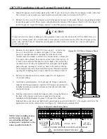
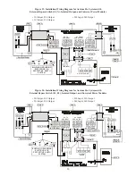
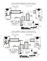
Figure 27: Installation Wiring Diagram for Axxium Pro Systems with

External Bypass Switch (L1, L2), Non-isolated Output, and Universal Power Modules

•  208 Input, 208 Output

•  230 Input, 230 Output

•  220 Input, 220 Output

•  240 Input, 240 Output

L2

N

N

L1

N

N

N

AC LINE INPUT

AC TO

UPS INPUT

AC FROM

UPS OUTPUT

AC TO LOADS

Note 2 

Per Local Code

Note 2 

Note 1 

Note 4 

Note 4 

TO

LOADS

Note 5 

Note 4  Note 9

1

3

LINE INPUT

X1

+DC

X2

N

-DC

OUTPUT POWER

2

Note 8

Note 9

L2

L1 L2

L1 L2

N

L1 L2

L1L2

L1

10 11 12 13 14 15 16

Note 7 

2 3 4

1

9

6 7 8

5

Note 4 

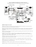
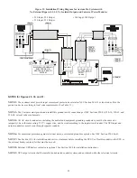
Figure 26: Installation Wiring Diagram for Axxium Pro Systems with

External Bypass Switch (L1, N), Non-isolated Output, and Universal Power Modules

•  220 Input, 220 Output

•  240 Input, 240 Output

•  230 Input, 230 Output

N

L1

N

N

N

AC LINE INPUT

AC TO

UPS INPUT

AC FROM

UPS OUTPUT

AC TO LOADS

Note 2 

Per Local Code

Note 2 

Note 1 

Note 4 

Note 4 

TO

LOADS

Note 5 

Note 4  Note 9 

1

3

LINE INPUT

X1

+DC

X2

N

-DC

OUTPUT POWER

2

Note 8

Note 9

N

L1

L1 L2

N

L1 L2

L2

L1 L2

L1

10 11 12

13 14 15

Note 7

2 3 4

1

9

6 7 8

16

5

Note 4 

Содержание 0650 SERIES

Страница 1: ...z Uninterruptible Power System User Installation Manual CONTAINS IMPORTANT SAFETY INSTRUCTIONS SAVE THESE INSTRUCTIONS Also refer to the Axxium Pro Fortress and UNITY I Safety Information manual ILS 1081 LTM 1327A Copyright 2000 Best Power All rights reserved ...

Страница 2: ...il sing service bestpower com Sola Australia Ltd 13 Healey Road Dandenong Victoria 3175 AUSTRALIA Telephone 61 3 9706 5022 Fax 61 3 9794 9150 E mail service solaaust com au Best Power Technology Limited BEST House Wykeham Industrial Estate Moorside Road Winchester Hampshire S023 7RX ENGLAND Telephone 44 1962 844414 Toll free 0800 378444 in England Fax 44 1962 841846 E mail uk service bestpower com...

Страница 3: ...rameters 14 402 Changing Parameter Settings 14 403 Reading the Axxium Pro System Logs 14 404 Menu Map 15 500 Alarms 17 501 Alarm Reason Codes 19 600 Communication 20 601 Communication Options 20 602 DB9 Port Pin Functions 21 700 Maintenance and Service 22 701 Routine Maintenance 22 702 Battery Replacement 22 703 Power Module Replacement 23 704 Service and Support 23 800 Specifications 23 900 Warra...

Страница 4: ...ontrol Panel 9 5 Communications Connector 10 6 Installing Modules 11 7 Axxium Pro System Menu Map 16 8 Typical Active Alarm Display 18 Tables 1 Control Panel Details 9 2 Inverter Log Reason Codes 15 3 Critical Alarm Messages 17 4 Non critical Alarm Messages 18 5 Alarm Reason Codes 19 6 DB9 Port Signals 21 7 Axxium Pro UPS Operating Specifications 25 ...

Страница 5: ...rth America contact your local sales office listed on the inside front cover of this manual You can also get more information about Best Power products using Best Power s Fax on Demand service U S A and Canada only or World Wide Web site Service Fax on Demand 1 608 565 9499 ext 9000 U S A and Canada World Wide Web Site http www bestpower com 101 Notices SAVE THESE INSTRUCTIONS This manual contains...

Страница 6: ...et senses problems in power modules and automatically transfers control to redundant modules All power modules share the load requirements equally For example three power modules are capable of supplying a total of 9 kVA If a load requires only 4 5 kVA each power module supplies 1 5 kVA to the output If one power module is removed or for some reason fails each of the two remaining power modules wo...

Страница 7: ... Features Front and Rear Views 3 slot cabinet 4 5 3 7 6 6 8 10 13 11 12 9 2 4 1 Battery Cabinet Rear View Power Module ASY 0528 and ASY 0567 Battery Module ASY 0529 Front and Rear Views 9 slot cabinet Legend 1 Operator Control Panel 5 Input Power Mains Cable optional 9 Secondary Stop Release 2 Front Cover Bezel 6 Battery Cabinet Cable optional 10 Latch Release 3 BestDock Ports 7 Cabinet Base 11 Ha...

Страница 8: ...with no interruption 0 ms transfer time as AC input power drops and returns Batteries are charged in this mode Battery mode produces power from the batteries to supply the internal DC bus Internal Bypass Bypass mode shunts power flow around the DC AC internal circuitry to keep the output powered with no line conditioning Electromagnetic interference EMI and surge circuitry still protect the loads ...

Страница 9: ...nnect load equipment to the UPS For information about installing or replacing batteries refer to Section 700 Maintenance and Service For information about connecting disconnecting external battery cabinets refer to Section 1400 1 2 3 4 A B C 4 24 USER 3 Wout watts 2 37 KW Slot Top ESC Item Description 1 Alphanumeric display of unit function and operating parameters Also displays alarm data logs 2 ...

Страница 10: ...nector on the back of the UPS Plug the other connector into the connector on the computer For instructions about installing the CheckUPS software refer to the information accompanying the CheckUPS CD ROM and Section 601 of this manual 3 INSTALL MODULES NOTE Place battery modules below all power modules in the UPS cabinet to maintain a low center of gravity CAUTION To avoid potential equipment dama...

Страница 11: ...upport rail NOTE Keep the module handle extended until the module is fully inserted Push the module in firmly The power module has a cam latch at the base of the handle raising the handle pulls the module into the rack A latch and thumbscrew at the top of the handle secure the handle Record all power module serial numbers on the warranty registration form see Section 903 3 d Insert and latch batte...

Страница 12: ...o scroll between English French German and Spanish Make your selection by pressing the Enter button 3 The next two screens enable you to verify and adjust the internal clock for the correct local time If the time or the date is correct as displayed press the Enter button to advance to the next configuration setting To set the correct time and date press the and buttons to move to the digits you wi...

Страница 13: ... drawing above Slot button A enables you to observe the operation of a specific power module the module in slot 3 in this case or the overall system selected as slot 0 Top button B takes you to the top item in the current menu level in this case 4 1 And ESC button C enables you to move out of the current menu level in this case to menu 4 During normal operation the display appears as shown below M...

Страница 14: ...ss to enter a new value and when you have changed the value press again to save the change 403 Reading the Axxium Pro System Logs The Axxium Pro system makes an entry in its logs each time it sounds an alarm or runs on battery power This information can help in diagnosing power problems You can display the UPS Inverter and Alarm logs on the unit s display panel these logs are in menu 9 Inverter Lo...

Страница 15: ...enu are secondary items each numbered by its location under the primary menu Use the various buttons as shown in the map to navigate to the desired parameter If you need to change the value of a parameter you must begin by entering the correct password value first Parameter values can be observed but most can not be changed even though you have entered the correct user password Reason Code Meaning...

Страница 16: ... Delay 7 1 9 EPO Mode 7 1 10Ext Bypass Mode Top ESC ESC ESC ESC 6 System Diagnostics 6 1 RO Value 6 2 Battery Results 6 3 Runtime at EOT 6 4 DC Volts at EOT 7 2 1 Const I Duration 7 2 2 Const V Duration 7 2 3 Eqlz Chrg Duration 7 2 4 Eqlz Chrg Interval 7 2 5 Inst Eqlz Duration 7 3 1 System VA Limit 7 3 2 Number Phases 7 3 3 Nominal Frequency 7 3 4 Nominal AC Vout 7 2 6 Test Interval 7 2 7 Test Tim...

Страница 17: ...dwide Service or your nearest Best Power office Low AC Out E The UPS has shut down because the output AC voltage is too low to provide power to the load Phone Best Power Worldwide Service or your nearest Best Power office High AC In S High AC Out F The AC input voltage is too high any further increase to the voltage may damage the UPS The UPS has shut down because the output AC voltage is too high...

Страница 18: ...the failed module Phone Best Power Worldwide Service or your nearest Best Power office If the voltage increases the alarm clears automatically If it drops further it will cause a Low Battery alarm S High AC Input acvin 300 V minacvin 9999 V maxacvin 0 V Table 4 Non critical Alarm Messages The drawing above shows a typical alarm display Critical alarms are annunciated by a constant Alarm LED and a ...

Страница 19: ...sion Auto mode Phone Best Power Worldwide Service or your nearest Best Power office T Call Service Precharge Failure A power module has detected an initialization sequence problem and will not start up Look in the alarm log for the slot number of the affected module Phone Best Power Worldwide Service or your nearest Best Power office U Low Redundancy Insufficient Batteries The UPS load exceeds 280...

Страница 20: ... and control of the UPS through a customer supplied Telecom Modem modem This unit also in the event of an alarm condition provides automatic notification via Controller phone pager e mail or fax Optional Internal This adapter provides the Axxium Pro system with its own ethernet network connection allowing BestLink it to be remotely monitored and controlled via industry standard internet browsers T...

Страница 21: ...at closes pulls to Common 15 seconds after the UPS switches to battery power 4 Common The ground reference for all input and output signals 5 Normally Open Low Battery Alarm Contact A normally open contact that closes pulls to Common to signal a Near Low Battery or Low Runtime alarm Values that affect this contact closure may be user programmed 6 Reserved 7 Immediate Shutdown Mode set by External ...

Страница 22: ...nician should do in a Preventive Maintenance check or to schedule Preventive Maintenance with a Best Power authorized field service representative call Best Power s Worldwide Service We ll be happy to help you 702 Battery Replacement Axxium Pro system batteries may be removed and replaced while the UPS is operating under load hot swapped with no loss of power to the load or damage to the batteries...

Страница 23: ...the safety stop on the center support rail NOTE Keep the module handle extended until the module is fully inserted Push the module in firmly The power module has a cam latch at the base of the handle raising the handle pulls the module into the rack Make sure the latch at the top of the handle snaps into place then turn the thumbscrew in the handle clockwise to hold the handle up 704 Service and S...

Страница 24: ...rature Operating 0 to 40 C 32 to 104 F Storage Temperature UPS containing battery modules 20 to 40 C 4 to 104 F UPS without batteries 40 to 60 C 40 to 140 F Relative Humidity 5 95 without condensation High Altitude Operation The maximum operating ambient temperature drops 1 C per 300 m above 1525 m 2 F per 1000 ft above 5000 ft Maximum operating elevation is 3050 m 10 000 ft Maximum non operating ...

Страница 25: ...220 40 8 110 220 81 42 230 39 240 37 5 120 240 75 37 5 100 200 120 60 208 57 6 220 54 4 110 220 108 56 230 52 240 50 120 240 100 50 100 200 150 75 208 72 220 68 110 220 135 70 230 65 240 62 5 120 240 125 62 100 200 180 90 208 86 4 220 81 6 110 220 162 84 230 78 240 12 5 120 240 150 75 Heat Dissipation in Double Conv Watts kBtu hr Efficiency in Bypass Mode Isolated Output Efficiency in Double Conve...

Страница 26: ...o conform to this warranty after a reasonable number of attempts BEST POWER will refund the purchase price Remedies under this warranty are expressly limited to those specified above TO THE EXTENT ALLOWED BY LAW BEST POWER DISCLAIMS ALL OTHER WARRANTIES EXPRESS OR IMPLIED INCLUDING BUT NOT LIMITED TO ANY IMPLIED WARRANTIES OF MERCHANTABILITY OR FITNESS FOR A PARTICULAR PURPOSE AND ANY IMPLIED WARR...

Страница 27: ...e or other casualty misuse negligence incorrect wiring and any use or installation not in conformance with instructions furnished by BEST POWER or repairs or replacements needed because of modifications or parts not authorized or supplied by BEST POWER This warranty is operable only upon the written acceptance by BEST POWER of an application by the PURCHASER on BEST POWER s standard form for the a...

Страница 28: ...ded in accordance with instructions supplied by Best Power _____________________________ ______________________ signature installation date Please print the Power Module following information Serial Numbers Contact Person _____________________________________ P Q 650 Title _____________________________________ P Q 650 Company _____________________________________ P Q 650 Street Address ___________...

Страница 29: ...les of all power modules out at least one inch 20 mm to turn off the power control circuitry If your UPS has external battery cabinets press the large red DC disconnect button on the back of the battery cabinet Turn off the alarm beeps Press the lower left button Note the alarm message and refer to the Alarm Messages table to correct the problem After the problem has been resolved press the lower ...

Страница 30: ... redundancy setting If you wish to change the number of redundant backup power modules press the Enter button change the value of the parameter and press the Enter button to store the displayed value Change the batteries Each side by side pair of battery modules forms one series string on the DC bus Refer to Section 702 for the battery replacement procedure Add delete one or more strings of batter...

Страница 31: ...al Bypass Switches 42 1303 Installation Overview 43 1304 Determining Input Output Voltage and Selecting Power Module Type 44 1305 Input Wiring Connections 45 1306 Neutral to Ground Bonding for Isolated Outputs 45 1307 Installation with an External Bypass Switch 46 1308 UPS Output Wiring Connections 48 1309 Balancing Receptacle Loads 58 1400 Connecting the External Battery Cabinets 59 Figures 9 UPS...

Страница 32: ... Wiring Diagram for Axxium Pro Systems with External Bypass Switch L1 L2 N Non isolated Output and Split phase Power Modules53 29 Installation Wiring Diagram for Axxium Pro Systems with No External Bypass L1 N Isolated Output and Universal Power Modules 54 30 Installation Wiring Diagram for Axxium Pro Systems with No External Bypass L1 L2 Isolated Output and Universal Power Modules 54 31 Installat...

Страница 33: ...s from side panels 6 in 152 mm Top and back 12 in 305 mm Front 36 in 915 mm If flexible conduit connects the UPS to the service and load distribution panels you may be able to gain access for servicing by moving the UPS If this is the case you must still leave 12 in 305 mm clearance at the back and 6 in 152 mm at the sides of the UPS for ventilation Do not block the ventilation holes on each side ...

Страница 34: ...uts on 6 slot cabinets along the front of the UPS chassis at location A as shown 5 Install a rack mount ear 2 for 6 slot cabinets on each side of the UPS chassis as shown in Figure 10b 5 a Insert the two offset tabs on the rear edge of the ear into matching slots B on the chassis side frame 5 b Pivot the ear forward until it is flush against the UPS chassis side frame 5 c Secure each ear with thre...

Страница 35: ... to Figure 12 is available for 3 slot and 6 slot cabinets It increases the mobility of the UPS if required NOTE The UPS chassis is heavy This procedure requires two people to lift and position the chassis into the caster cart Lift the cabinet using four lifting straps shipped with the cabinet do not attempt to lift the cabinet by the module shelves or other convenient edges or panels The caster ca...

Страница 36: ...ly 12 16 in 30 41 cm apart at the floor wall intersection behind the intended cabinet location 2 Using the proper type of customer supplied screws for the intended mounting surface attach each bracket as shown in Figure 13 Make sure that all screws are driven into structural material such as wall studs 3 Roll the UPS cabinet to its intended location positioning the rear section of the cabinet base...

Страница 37: ...t from rolling when properly positioned The larger 9 slot and 12 slot cabinets have casters built into the cabinet base Use the procedure below to raise the cabinet before rolling it on its casters For 12 slot cabinets that do not have output isolation refer to Section 1106 for details about mounting stabilizer brackets before rolling the cabinet into place 1 Ensure that the cabinet contains no ba...

Страница 38: ...of the UPS or the load distribution panel The bypass switch has four positions as described in Table 9 In the UPS or LINE position AC input power is still connected to the input terminals inside the UPS To disconnect AC input power during maintenance or service turn the bypass switch to the SERVICE position For Make Before Break switches you must press the red button beside the switch before you c...

Страница 39: ...PS are available in six models as specified in Table 10 Table 10 Bypass Switch Specifications 53 24 1 6 6 168 18 4 467 26 5 673 150A 300VAC BPE22BBM1A break before make BPE22MBB1A make before break 31 14 1 6 8 172 14 0 356 21 0 534 80A 300VAC BPE14BBM1A break before make BPE14MBB1A make before break 27 12 3 6 8 172 14 0 356 21 0 534 40A 300VAC CSA 50A 300VAC UL TÜV BPE12BBM1A break before make BPE...

Страница 40: ...nal caster cart is included for cabinet mobility refer to Section 1105 for information about mounting the cabinet on the cart and stabilizing it using the cart foot pads 5 After placing the cabinet in its intended operating location cut the lifting straps or slip them off the cabinet base tabs 6 If the cabinet does not have a line mains power cord install the input power conduit or cabling between...

Страница 41: ...15 and Section 1303 8 If the cabinet has a line mains power cord plug the cord into a mains power outlet 9 Refer to Section 300 for instructions to install power and battery modules 10 Test proper operation of external control signals and computer communication before connecting loads 1300 UPS and Bypass Switch Installation for Qualified Personnel Only 1301 Input Current Ratings Table 11 contains ...

Страница 42: ...all connections by tightening all screws to the torque values specified in Table 12 Table 12 United States Recommended AWG and mm2 Wire Sizes For U S installations read this Important Note This table lists the AWG and mm2 wire size for each circuit breaker size shown on the wiring diagrams The minimum recommended circuit breaker sizes for each model and voltage application are listed on the wiring...

Страница 43: ...or supplied to loads through receptacles on the back of the UPS Without a bypass switch power to the load cannot be maintained if the UPS is taken completely offline The UPS input mains connection may also be made through a power cord plugged into a mains receptacle In such an installation the UPS must be installed near the mains input power receptacle and the plug must be readily accessible In th...

Страница 44: ... L2 N L1 L2 N L1 L2 N L1 L2 N L1 L2 N L1 L2 N L1 L2 L1 L2 L1 L2 L1 L2 L N L N L N L1 L2 N No No No No No No No No No No No No No No No Yes No No No No No No No No No No No No 34 34 34 34 34 33 33 33 33 32 32 32 16a 22d 16a 22d 16a 22d 16a 22e 16a 22e 16a 22e 16a 22e 16a 22c 16a 22c 16a 22c 16a 22d 31 31 31 30 30 30 30 29 29 29 25 Yes Yes Yes Yes Yes Yes Yes Yes Yes Yes Yes 16b 22b 16b 22b 16b 22b ...

Страница 45: ...module Figure 16 Input Wiring of Axxium Pro UPS 1306 Neutral to Ground Bonding for Isolated Outputs As required under safety regulations issued by various regulatory agencies the UPS cabinet must have a ground bond connection for the neutral terminal of an isolated output system In such a system the customer must make the neutral to ground also referred to as N G or neutral to earth connection aft...

Страница 46: ... AC input and AC output wiring 5 Install the conduit adapters AC Input and AC Output conductors must be run through separate conduits UPS output circuits must be installed in dedicated conduit systems and not shared with other electrical circuits 6 Find the terminal strip inside the bypass switch Using the label on the back of the bypass switch access panel and the proper Installation Wiring Diagr...

Страница 47: ... and locate the terminal block as shown in Figure 21 CAUTION EPO and external bypass circuits are not isolated from line voltage and wiring must be installed per local codes using conduit or suitable primary supply cables The Generator On signal is isolated from line voltage and can be treated as NEC Class 2 wiring Use 14 20 AWG 600 V wire UL or 14 26 AWG 300 V wire CSA for all input control signa...

Страница 48: ...00 220 208 or 240 as required X X X 200 220 100 110 127 208 or 240 or 120 100 110 127 or 120 L2 L1 N X1 X3 X0 X2 50 or 60 Hz 208 220 230 or 240 V Out with Isolated Output Option Parameter 7 3 4 set to 208 220 230 or 240 as required Note If required provide N G bond to create voltage to earth reference X X N G Bond L1 N X1 X3 X0 X2 50 or 60 Hz 110 220 or 120 240 V Out with Isolated Output Option Pa...

Страница 49: ... X3 X0 X2 50 or 60 Hz 208 220 230 or 240 V Out with Isolated Output Option Parameter 7 3 4 set to 208 220 230 or 240 as required X X L1 L2 Figure 22e Universal Modules With 2 wire Plus Ground Isolated Output ...

Страница 50: ...YSTEM N L1 N N N AC LINE INPUT AC TO UPS INPUT AC FROM UPS OUTPUT AC TO LOADS Note 2 Note 3 Per Local Code Note 2 Note 1 Note 4 Note 4 TO LOADS Note 5 Note 4 Note 9 LINE INPUT OUTPUT POWER 2 Note 8 Note 6 Note 9 N L1 L2 L1 L2 N L1 L2 L1 L2 L1 10 11 12 13 14 15 16 Note 7 2 3 4 1 9 6 7 8 5 1 3 Note 4 X1 X3 X0 X2 BUILDING GROUNDING ELECTRODE OR PROTECTIVE EARTH SYSTEM L2 N N N X1 X3 X0 X2 AC LINE INP...

Страница 51: ...ust be connected as described in step 9 of Section 1304 NOTE 3 The Customer must provide and install this ground earth connection per NEC Sections 250 20 250 30 250 62 and 250 64 or local code requirements NOTE 4 All AC circuit conductors including the neutral and equipment grounding conductors must be the same size ampacity have the same rating 75 ºC copper wire and be sized according to the inpu...

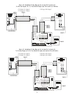
Страница 52: ... DC OUTPUT POWER 2 Note 8 Note 9 L2 L1 L2 L1 L2 N L1 L2 L1L2 L1 10 1112 13 14 15 16 Note 7 2 3 4 1 9 6 7 8 5 Note 4 Figure 26 Installation Wiring Diagram for Axxium Pro Systems with External Bypass Switch L1 N Non isolated Output and Universal Power Modules 220 Input 220 Output 240 Input 240 Output 230 Input 230 Output N L1 N N N AC LINE INPUT AC TO UPS INPUT AC FROM UPS OUTPUT AC TO LOADS Note 2 ...

Страница 53: ...t of the UPS To properly install complete the voltage and phase check procedure in Section 1304 The wires coming from the side of the switch must be connected as described in step 9 of Section 1304 NOTE 4 All AC circuit conductors including the neutral and equipment grounding conductors must be the same size ampacity have the same rating 75 ºC copper wire and be sized according to the input circui...

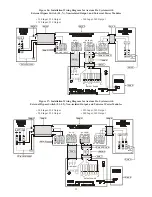
Страница 54: ...e 4 Note 9 LINE INPUT OUTPUT POWER 2 Note 8 Note 6 Note 9 N L1 Note 7 L1 1 3 X1 X3 X0 X2 Figure 30 Installation Wiring Diagram for Axxium Pro Systems with No External Bypass L1 L2 Isolated Output and Universal Power Modules 208 Input 208 Output 230 Input 230 Output 220 Input 220 Output 240 Input 240 Output BUILDING GROUNDING ELECTRODE OR PROTECTIVE EARTH SYSTEM L2 N L1 X1 X3 X0 X2 Note 3 Per Local...

Страница 55: ...h connection per NEC Sections 250 20 250 30 250 62 and 250 64 or local code requirements NOTE 4 All AC circuit conductors including the neutral and equipment grounding conductors must be the same size ampacity have the same rating 75 ºC copper wire and be sized according to the input circuit breaker The UPS input and output conductors must be run through separate conduits NOTE 6 For maximum protec...

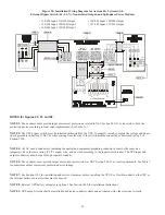
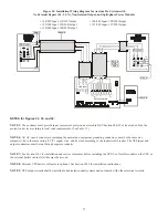
Страница 56: ... LOADS Note 4 Note 9 1 3 LINE INPUT X1 DC X2 N DC OUTPUT POWER 2 Note 8 Note 9 N L1 Note 7 Figure 33 Installation Wiring Diagram for Axxium Pro Systems with No External Bypass L1 L2 Non isolated Output and Universal Power Modules 208 Input 208 Output 230 Input 230 Output 220 Input 220 Output 240 Input 240 Output L2 L1 Per Local Code Note 1 Note 4 TO LOADS Note 4 Note 9 1 3 LINE INPUT X1 DC X2 N DC...

Страница 57: ... the protection device according to local code requirements See Table 11 NOTE 4 All AC circuit conductors including the neutral and equipment grounding conductors must be the same size ampacity have the same rating 75 ºC copper wire and be sized according to the input circuit breaker The UPS input and output conductors must be run through separate conduits NOTE 7 See Section 1101 for installation ...

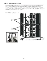
Страница 58: ...as possible Whether the cabinet has one panel containing eight receptacles two panels containing 16 receptacles or three panels containing 24 receptacles you should try to supply half of the UPS output through the upper half of the receptacles X1 and the other half through the lower half of the receptacles X2 as shown in Figure 35 Figure 35 Balancing Receptacle Loads X1 X2 X1 X2 ...

Страница 59: ...he compression lug onto the DC bolt of the bus bar extension assembly Secure the assembly by replacing the two nuts removed in the previous step 7 Use the bolt and nut supplied with the cable assembly to attach the ring terminal to the empty hole in the DC bus bar 8 Torque all three bolts to 75 85 in lb 8 5 9 6 Nm 9 Loosen the three large nuts at one end of the cable assembly The two cable ends ar...

Страница 60: ...f an additional battery cabinet will be connected to the first in a series connected daisy chain configuration use another external battery cabinet cable assembly for the connections between the battery cabinets Locate the daisy chained cable on the rear of the first battery cabinet in the bay below the location of the first cable assembly Follow this procedure for connecting any additional daisy ...

Отзывы: