5 Commissioning
LB 571 BTwave
18
68847BA2 Rev.00, 10/2020
3.
Connect cables to the terminals according to the connection diagram. Ob-
serve the information in chapter 5.2 Cables and wires.
IMPORTANT
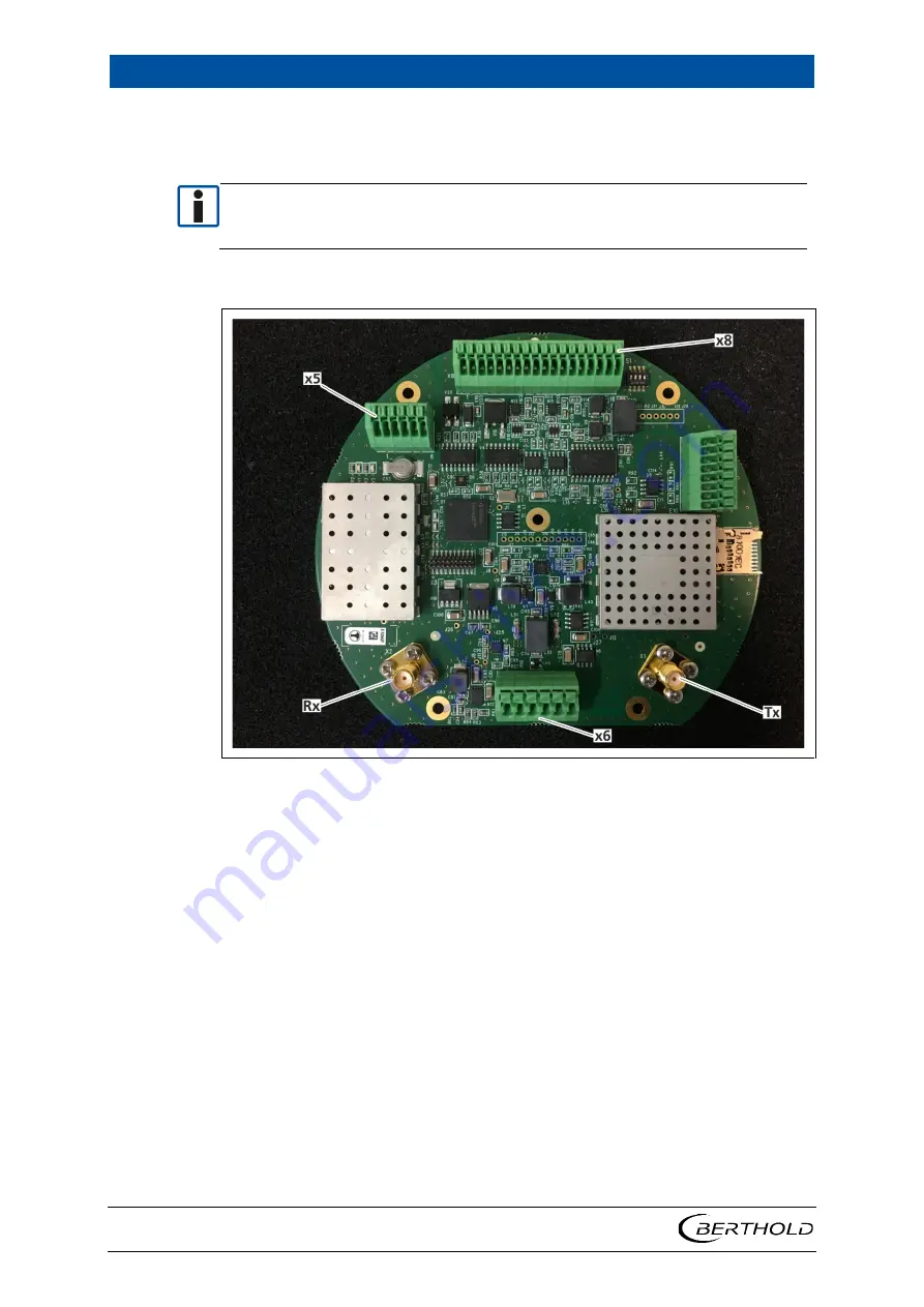
Connectors marked on Figure 7 are in use. Pin number 1 is always on left side as
shown on connector X8. Connector interfaces are shown on the table next
page.
Connector Pin Assignment
Figure 7 LB 571 Pin assignment
4.
Make sure that all lines are correctly connected and routed.
5.
Tighten the cap nuts of the cable glands (Figure 6, Pos.4) with a tightening
torque of 5.5 Nm.
6.
Make sure there is a locking washer (Figure 6, Pos.2) on each hex socket
screw (Figure 6, Pos.1).
7.
Make sure that the entire circumference of the O ring seal (Figure 6, Pos.5)
is undamaged and correctly inserted in the cover.
8.
Attach the cover (Figure 6, Pos.3) and tighten all screws with a tightening
torque of 1.5 Nm.
The electrical installation was carried out correctly.
Содержание BTwave LB 571-02
Страница 1: ...BTwave LB 571 02 Operating Manual 68847BA2 Rev No 00 01 2020 ...
Страница 2: ......
Страница 4: ......
Страница 24: ...5 Commissioning LB 571 BTwave 20 68847BA2 Rev 00 10 2020 ...
Страница 44: ...7 Diagnostics LB 571 BTwave 40 68847BA2 Rev 00 10 2020 ...
Страница 48: ...8 Error Codes and Alarms LB 571 BTwave 44 68847BA2 Rev 00 10 2020 ...
Страница 50: ...9 Technical Information LB 571 BTwave 46 68847BA2 Rev 00 10 2020 ...
Страница 51: ...LB 571 BTwave 10 Declaration of Conformity 68847BA2 Rev 00 10 2020 47 10Declaration of Conformity ...


