background image

E

3

2. Wall Construction 

This Built-In Microwave Hood should be mounted against and 

supported by a flat vertical wall. The wall must be flat for proper 

installation. If the wall is not flat, use spacers to fill in the gaps. 
Wall construction should be a minimum of 2” x 4” wood 

studding and 

3

/

8

” or more thick drywall or plaster/lath. The 

mounting surfaces must be capable of supporting a weight of 

110 pounds—the oven and contents—AND the weight of all 

items that would normally be stored in the top cabinet above 

the unit. The unit should be attached to a minimum of one 2” 

x 4” wall stud.
To find the location of the studs, one of the following methods 

may be used:
•  Use a stud finder, a magnetic device which locates the nails 

in the stud.

•  Use a hammer to tap lightly across the mounting surface 

to find a solid sound. This will indicate stud location. 

The center of the stud can be located by probing the wall with 

a small nail to find the edges of the stud and then placing a 

mark halfway between the edges. The center of any adjacent 

studs will normally be 16” or 24” to either side of this mark.

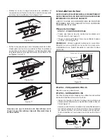
2"x 4" Wood Studs

or Plaster/Lath

3/8" Dry Wall 

16" or 24"

Figure 2

NOTE:

 In the event that the unit will be unable to be supported 

by any stud, it will be necessary to use special care in the 

placement of the toggle bolts and top cabinet screws. See 

Wall Template for details. The top cabinet should be tested to 

ensure it is securely attached to the wall. Place extra weight 

up to 110 pounds inside the top cabinet to test the support.

3. ELECTRICAL GROUNDING 

INSTRUCTIONS

This appliance must be grounded. This oven is equipped with 

a cord having a grounding wire with a grounding plug. It must 

be plugged into a wall receptacle that is properly installed and 

grounded in accordance with the National Electrical Code and 

local codes and ordinances. In the event of an electrical short 

circuit, grounding reduces risk of electric shock by providing 

an escape wire for the electric current.

WARNING

 - Improper use of the grounding plug can result in 

a risk of electric shock.
The Power Supply Cord and plug must be connected to a 

dedicated 120 Volt AC, 60 Hz, 15 Amp, or more branch circuit, 

single grounded receptacle.

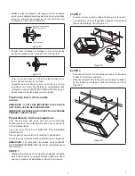
Ground

Receptacle

Opening for

Power Cord

Figure 3

NOTE:

1.  If you have any questions about the grounding or electrical 

instructions, consult a qualified electrician or serviceperson.

2.  Neither Bertazzoni nor the dealer can accept any liability for 

damage to the oven or personal injury resulting from failure 

to observe the correct electrical connection procedures.

Содержание KOTR30MXE

Страница 1: ...E 1 OVER THE RANGE MICROWAVE OVEN INSTALLATION GUIDE Model KOTR30MXE TINSEB586MRR0 ...

Страница 2: ...wall of the oven cavity Check to see that there is a Wall Template and Top Cabinet Template Read enclosures and SAVE the Use and Care manual Check the oven for any damage such as misaligned or bent door damaged door seals and sealing surfaces broken or loose door hinges and latches and dents inside the cavity or on the door If there is any damage do not operate the oven and contact your dealer or ...

Страница 3: ... the unit will be unable to be supported by any stud it will be necessary to use special care in the placement of the toggle bolts and top cabinet screws See Wall Template for details The top cabinet should be tested to ensure it is securely attached to the wall Place extra weight up to 110 pounds inside the top cabinet to test the support 3 ELECTRICAL GROUNDING INSTRUCTIONS This appliance must be...

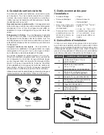
Страница 4: ...d total less than 140 feet Figure 4 5 Tools Recommended for Installation Phillips Screwdriver Electric Drill Scissors Saw to cut exhaust opening if needed 11 2 Wood Bit or Metal Hole Cutter if metal cabinet is used Pencil Measure Tape 1 2 5 8 and 3 32 Drill Bits Protective Drop Cloth for product and range you may also use carton for protection 6 Installation Hardware The following is a list of par...

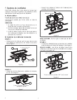
Страница 5: ... blower unit out of mounting location See Figure 8 Blower motor Figure 8 CAUTION Do not pull or stretch blower wiring STEP 3 Turn the blower unit so that the fan blade openings are facing back rear of unit See Figure 9 CAUTION Wires to blower unit must be routed properly to avoid pinching wires before reinstallation of cover plate After Fan blade openings facing Rear Figure 9 Use side cutters or t...

Страница 6: ...stem The unit is shipped assembled for recirculating STEPS 1 2 A 1 Ventilation motor See Section B steps 1 and 2 for access to the blower motor Also see Figure 8 STEP 3 Turn the blower unit so that the fan blade openings are facing upward See Figure 14 Fan Blade Openings Facing Up After Turning Back of Oven Figure 14 STEP 4 Place the blower unit into the opening Secure the Blower Motor Cover to th...

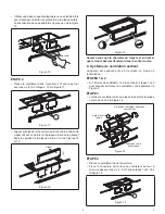
Страница 7: ...e wall template for the rear wall Reference Wall Template prior to proceeding Installation of this product requires 2 people A C C B C C Power Supply Cord Hole House Duct Mounting Plate Figure 18 STEP 2 DRILLING Reference the Wall Template STEP 3 TIGHTENING THE SCREWS To attach the mounting plate to the wall using the toggle bolt assemblies and or lag screws Insert toggle bolts through mounting pl...

Страница 8: ... TOP CABINET TEMPLATE Tape it underneath the top cabinet Drill the holes following the instructions on the template NOTE TOP CABINET TEMPLATE instruction must be installed to proceed STEP 1 Protect the top of your range by placing a portion of the carton or some other heavy material over the cooking surface before mounting your oven STEP 2 Lift the microwave oven and tilt it forward Hang the unit ...

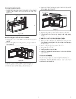
Страница 9: ... place The filter should rest at the angle See Figure 27 Charcoal Filter Grille Air Figure 27 6 Replace the grille air and 3 screws and close the door 7 Plug the oven in or turn on the power at the main power supply CHECK LIST FOR OPERATION 1 Make sure the unit has been installed according to all of the Installation Instructions the Top Cabinet Template and Wall Template 2 Remove all packing mater...

Страница 10: ...1 F FOUR À MICRO ONDES MONTÉ AU DESSUS D UNE CUISINIÈRE GUIDE D INSTALLATION Modèle KOTR30MXE ...

Страница 11: ...èle de mur et un modèle d armoire supérieure Lisez les pièces jointes et CONSERVEZ le manuel d utilisation et d entretien Vérifiez que le four ne présente aucun dommage tel qu une porte mal alignée ou déformée des joints d étanchéité de la porte et des surfaces d étanchéité endommagés des charnières et des loquets de porte cassés ou desserrés ainsi que des bosses dans la cavité ou sur la porte En ...

Страница 12: ...reil à un montant du mur il faudra porter une attention particulière au placement des ancrages à boulon et des vis pour l armoire supérieure Consultez le Gabarit mural pour les détails L armoire supérieure devrait être testée pour vérifier qu elle est solidement fixée au mur Placez jusqu à 110 livres 50 kg de poids supplémentaire dans l armoire supérieure pour tester sa capacité de soutien 3 INSTR...

Страница 13: ...es sections de tuyau droites La Figure 4 montre la longueur équivalente approximative en pieds des pièces de conduit communes Utilisez les valeurs entre parenthèses pour calculer la longueur totale équivalente qui devrait être inférieure à 140 pieds COUDE 90 º 10 PI COUDE 90 º 25 PI COUDE 10 PO DE LARGE 10 PI SORTIE DE TOIT 24 PI COUDE 45 º 5 PI COUDE 45 º 5 PI SORTIE MURALE 40 PI ADAPTATEUR 5 PI ...

Страница 14: ...ez les vis 1 et 2 pour ouvrir le couvercle du moteur du ventilateur et conservez ces vis Retirez le couvercle Voir la Figure 6 Couvercle du moteur du ventilateur Arrière du FOUR Figure 6 ÉTAPE 2 Retirez les vis 3 de fixation du ventilateur et conservez les vis Voir la Figure 7 Avant Ouvertures du ventilateur orientées vers l avant Figure 7 Soulevez le ventilateur et retirez le de l emplacement de ...

Страница 15: ...re 13 Assurez vous que la charnière du clapet est en haut et que le clapet bascule librement dans la sortie murale C Système de ventilation vertical L appareil est expédié prêt à être utilisé en mode de recirculation ÉTAPES 1 2 A 1 Moteur de ventilation Voir la section B étapes 1 et 2 pour accéder au moteur du ventilateur Voir également la Figure 8 ÉTAPE 3 Tournez le ventilateur afin que les sorti...

Страница 16: ...e de montage ÉTAPE 1 POSITION DE MONTAGE Tracez une ligne le long du centre des montants voir Construction du mur page 1 Tracez une ligne verticale sur le mur au centre de l espace de 30 po Voir la Figure 18 REMARQUE Utilisez le gabarit mural pour le mur arrière Reportez vous au gabarit mural avant de poursuivre L installation de ce produit nécessite le concours de deux personnes A C C B C C Orifi...

Страница 17: ...L INSTALLATION Préparation de l armoire supérieure Vous devez percer des trous pour les vis de montage supérieures et un trou suffisamment grand pour y passer le cordon d alimentation Lisez les instructions sur le GABARIT DE L ARMOIRE SUPÉRIEURE Fixez le gabarit sous l armoire à l aide de ruban adhésif Percez les trous conformément aux instructions sur le gabarit REMARQUE Les instructions imprimée...

Страница 18: ...omment remplacer le filtre à charbon 1 Débranchez le four à micro ondes ou coupez le courant directement au panneau de distribution électrique 2 Retirez les 3 vis de montage de la grille d aération et ouvrez la porte Voir la Figure 26 Figure 26 3 Glissez la grille à air vers la gauche puis tirez pour l enlever 4 Poussez le filtre à charbon vers l arrière et retirez le 5 Glissez en place un filtre ...

Страница 19: ...rer du four le matériel d emballage restant 3 Brancher le cordon d alimentation 4 Lire le Manuel d utilisation 5 Garder toutes les instructions d installation à l intention de l inspecteur en électricité ACCESSOIRES Consultez votre revendeur ou commandez directement du Centre à fournitures et accessoires de Bertazzoni FILTRE À CHARBON CFOR3 Le filtre est utilisé uniquement lorsque l échappement es...

Страница 20: ...BERTAZZONI SPA VIA PALAZZINA 8 42016 GUASTALLA RE ITALY WWW BERTAZZONI COM ...

Отзывы: